Face mask for use in pressurized drug delivery systems

a technology for delivering systems and drugs, applied in the field of masks, can solve the problems of increased facial deposition of drugs, and potential local side effects, and achieve the effects of reducing the inertia of aerosolized drugs, and reducing the amount of aerosolized drugs

Inactive Publication Date: 2006-08-01
SMALDONE GERALD C
View PDF14 Cites 10 Cited by
  • Summary
  • Abstract
  • Description
  • Claims
  • Application Information

AI Technical Summary

Benefits of technology

[0022]In one exemplary embodiment, a face mask for use in pressurized drug delivery applications, such as aerosol drug delivery systems, and a method of reducing aerosol deposition in the region of the eyes are presented. The face masks according to the various embodiments disclosed herein contain features that reduce the inertia of the aerosolized drug in perinasal areas. This results in a reduction in the amount of aerosolized drug that is deposited in the region of the eyes by inertial impaction, while at the same time, the features are constructed to maintain the flow of the aerosolized drug into the face mask so that the aerosolized drug is effectively delivered to the respiratory system of the patient.
[0023]According to one exemplary embodiment, the face mask has a body having a bottommost edge or surface for placement against a face of a patient. A nose bridge section is formed in an upper section of the mask body to seat against the nose of the patient when the mask is placed against the face during the application. The body has a pair of eye vents formed therein, with one eye vent being formed on one side of the nose bridge section and the other eye vent being formed the other side of the nose bridge section. When the face mask is worn by the patient, the eye vents are generally orientated underneath the eyes of the patient. The eye vents are thus eye cut outs or openings formed along the peripheral edge of the mask body by removing mask material. The present applicant has found that opening the face mask at the sites of the greatest risk (i.e., the eyes), where aerosolized drug flow is not desired, compels and ensures the local reduction of particle inertia at the sites most at risk of facial damage and irritation. The excisions in the face mask that serve as eye vents thus minimize the local velocity and particle inertia such that the particles do not impact on the surface of the face and eyes and actually pass over the face and eyes without deposition thereon as shown by arrows in FIG. 3. This results in a substantial reduction of deposition in the region of the eyes compared to conventional face masks.
[0024]The eye cut outs or openings can be formed in any number of different sizes and any number of different shapes (e.g., semicircular) based upon the performance characteristics (i.e., inhaled mass value, facial deposition amount, etc.) that are desired in the application of the aerosolized drug. The eye vents can also be used in combination with a supplemental vent that is also formed in the face mask body. For example, the supplemental vent can be in the form of an opening that is formed in the mask in a lower chin section near the peripheral edge. By providing eye vents in the face mask, a face mask is provided that substantially alleviates or eliminates the discomfort and potential harmful consequences that are associated with face masks that have leaks in the perinasal areas which result in the aerosolized drug being “funneled” between the peripheral edge of the face mask and the face and causing the aerosolized drug to flow at great velocities into the eyes of the patient.
[0025]Moreover, by optimizing the distance from the face to a point of insertion of the nebulizer within a connection portion of the mask, a reduction in the inertia of the aerosolized drug in the perinasal areas is realized as well as across the face and this results in a reduction in the amount of aerosolized drug deposited on the face, including in the eye regions.

Problems solved by technology

Nebulizers readily pressurize the mask and deliver more drug but leaks around the face are enhanced, resulting in increased facial deposition of the drug.
Thus, leakage around the mask affects the performance of the particular device and in the case of nebulizers, leakage actually enhances the delivery of the drug; however, it is enhanced at the price of increased facial deposition and potentially local side effects.
For nebulizers, this produces certain leakage areas where the aerosolized drug can be discharged underneath the face mask and into the atmosphere.
Because of the design of face masks and their above-described placement over the face, leakage is universally present in the perinasal areas on either side of the nose.
In other words, aerosol is discharged underneath the face mask in these perinasal areas and flows directly towards the patient's eyes and unfortunately, many of the conventional masks are constructed in such a manner that the leaks that do occur are characterized as being high powered leaks (high kinetic energy) due to the high velocity that the fluid has as it flows underneath the mask and along the face directly into the eyes.
This may lead to several undesired side effects.
For example, deposition of the leaked aerosolized drug may be associated with direct trauma to the eyes and associated structures.
There is speculation that the risk of developing cataracts increases as a result of aerosolized drugs being directly deposited in the eyes of the patient.
At the very least, leakage of aerosolized drugs causes discomfort as the aerosol, traveling at a great velocity, is discharged underneath the face mask and deposits in the perinasal areas, including the eyes.
In addition, leaks of certain aerosols can cause dermatological problems in some patients due to an adverse reaction between facial skin and the aerosol.
Other undesirable conditions may result from having the aerosolized drug leaking and being deposited onto the face.
The disadvantages associated with conventional mask constructions are readily apparent by viewing FIGS. 1, 1a and 2. FIG. 1 is a front perspective view of a typical face mask 100 (that is commercially available from Laerdal Medical Corporation of Wappingers Falls, N.Y.).
The perinasal areas 105 are particularly prone to the formation of leaks and this results in the aerosolized drug being discharged directly into the eyes and the associated structures.
This results in some of the aerosolized drug being lost into the surrounding environment.
It has also been found that the degree of pressure applied to the mask in an attempt to improve the seal between the face mask and the face does not necessarily improve and may in fact worsen the leakage of the aerosolized drug in the perinasal areas when the patient inhales and draws the aerosolized drug into the face mask reservoir.
For example a caregiver pressing on the mask can seal leaks along the cheeks but promote leaks around the eyes.
The leakage of the aerosolized drug in the perinasal areas results in the aerosolized drug being discharged towards the eyes of the patient at high velocities due to the high kinetic energy of the fluid.
This is less than ideal as it may cause discomfort at the very least and may also lead to other medical complications due to the drug being discharged into the eyes of the patient.
Eye deposition is thus particularly a problem for those drug delivery systems that exert greater pressure on the face mask and / or maintain the face mask reservoir under pressure.
While face masks having been developed with venting mechanisms to cope with the pressurization requirements of a nebulizer or the like, these face masks still suffer from the disadvantage that they have constructions that not only permit aerosolized drug to be discharged in the perinasal areas but more importantly, the aerosolized drug is discharged at high velocities toward the eyes due to the imperfect interface between the face mask and the face.

Method used


Image

  • Face mask for use in pressurized drug delivery systems
  • Face mask for use in pressurized drug delivery systems
  • Face mask for use in pressurized drug delivery systems

Examples


example 1

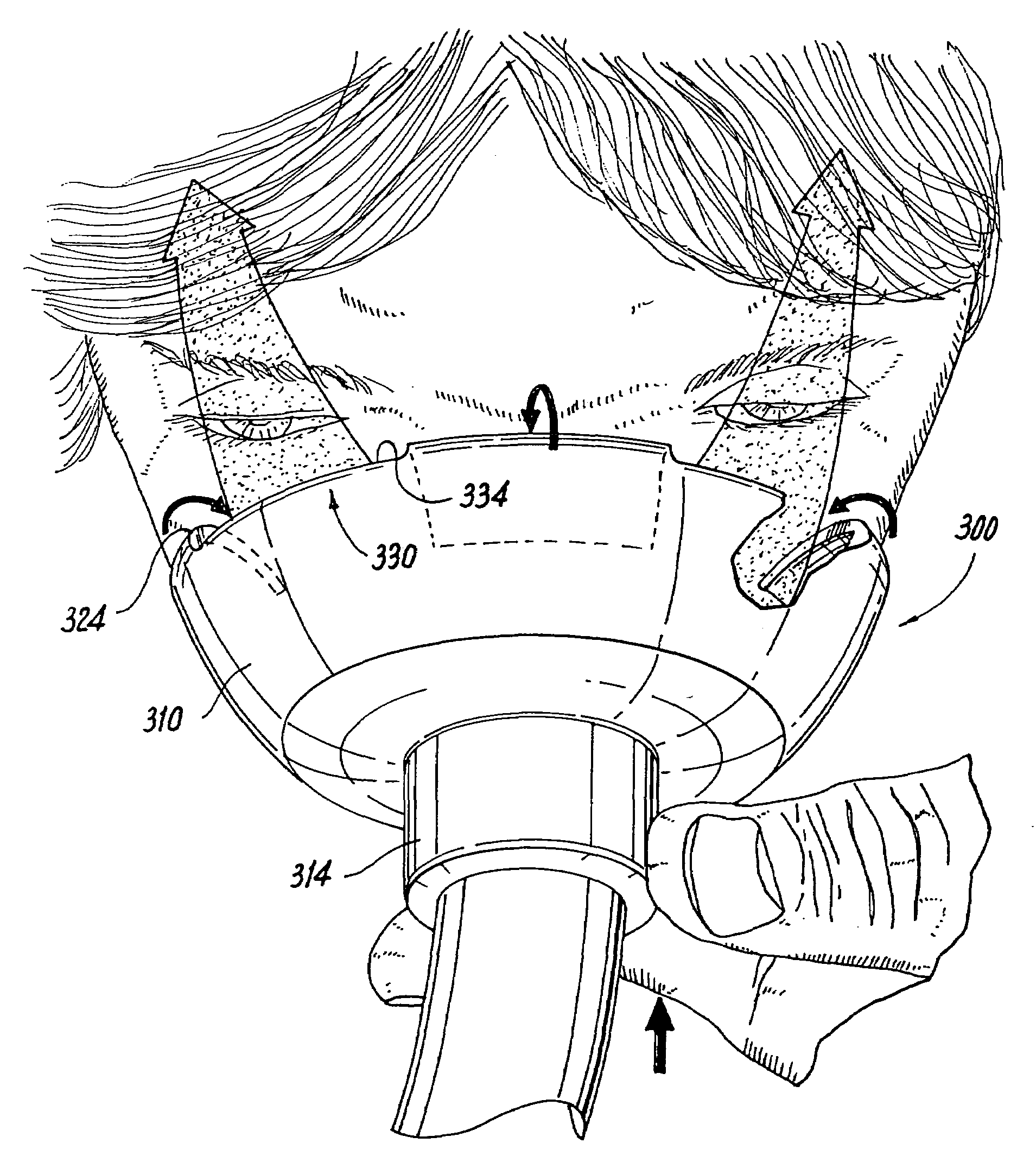
[0083]A face mask as shown in FIGS. 3–5 according to the first embodiment was constructed and has the following dimensions. An outer diameter of the mask body 310 is about 77 mm and an outer diameter of the flange 314 being about 20 mm. The second opening 320 has a diameter of about 46 mm. As will be appreciated by viewing the figures, the eye vents 330 have a tapered construction in that a width thereof is greatest at the inner edge 334 and is less where the eye vent 330 communicates with the second opening 320. According to one embodiment, the width of the eye vent 330 at the inner edge 334 is about 20 mm and then it tapers to a diameter of about 10 mm where the vent opening 330 communicates with the second opening 320. The depth of the eye vent 330 as measured from the inner edge 334 to the bottommost portion 324 is about 9 mm in the relaxed state shown in FIGS. 3–4 and when applied to the face during administration of the drug, the depth decreases to about 5 mm.

example 2

[0084]A face mask as shown in FIGS. 6–8 according to the first embodiment was constructed and has the following dimensions. The face mask has the same dimensions as set forth in Example 1 above with the following exceptions. The depth of the eye vent 330 as measured from the inner edge 334 to the bottommost portion 324 is about 27 mm in the relaxed state shown in FIGS. 3–4 and when applied to the face during administration of the drug, the depth decreases to about 17 mm.

[0085]It will be appreciated that during application, the depth of the eye vent 330 or eye vents 340 in the embodiment inFIGS. 9–11 decreases any where from about 30% to 70% relative to its original depth, and according to one embodiment. In another embodiment, the depth decreases from about 40% to about 60% of its original depth, e.g., about 50%.

[0086]The present applicant has determined that the major determinant of facial deposition during inhalation of aerosolized drug using a pressurized wet nebulizer system is ...


PUM


Abstract

Face masks for use in pressurized drug delivery applications, such as aerosol drug delivery systems, and a method of reducing aerosol deposition in the region of the eyes are presented. The face masks according to the various embodiments disclosed herein contain features that reduce the inertia of the aerosolized drug in perinasal areas. This results in a reduction in the amount of aerosolized drug that is deposited in the region of the eyes by inertial impaction, while at the same time, the features are constructed to maintain the flow of the aerosolized drug into the face mask so that the aerosolized drug is effectively delivered to the respiratory system of the patient.

Description

CROSS REFERENCE TO RELATED APPLICATIONS[0001]The present application claims the benefit of U.S. patent application Ser. No. 60 / 515,382, filed Oct. 29, 2003, and U.S. patent application Ser. No. 60 / 566,117, filed Apr. 27, 2004, both of which are hereby incorporated by reference in their entirety.BACKGROUND[0002]1. Technical Field[0003]The present invention relates to a mask and more particularly, to a face mask for use in delivering an aerosolized drug or the like to a patient.[0004]2. Description of Related Art[0005]Masks are commonly used in a wide range of applications and have widespread use in a number of medical settings. For example, masks are typically used in administering gases to a patient, e.g., an anesthetic agent, and more recently, masks have been increasingly used in drug delivery systems, including nebulizer drug delivery systems and metered dose inhalers using valved holding chambers (MDI / VHC). Nebulization is the application of a drug to a patient by means of an ae...

Claims


Application Information

Patent Timeline
Patent Type & Authority Patents(United States)
IPC IPC(8): A62B18/08A62B18/02A61M11/00A61M15/00A61M16/00A61M16/06
CPCA61M16/0616A61M16/06A61M11/00A61M15/00
Inventor SMALDONE, GERALD C.
Owner SMALDONE GERALD C
Why Eureka
Try Eureka