Attachment structure of a component in a fuel tank made of resin

Inactive Publication Date: 2006-08-01
YACHIYO IND CO LTD +2
View PDF8 Cites 9 Cited by
  • Summary
  • Abstract
  • Description
  • Claims
  • Application Information

AI Technical Summary

Benefits of technology

[0011]In accordance with the structure a seal property can be improved and strength, rigidity, and a high

Problems solved by technology

However, the structure of making the O-ring 52 intervene results in causi

Method used


Image

  • Attachment structure of a component in a fuel tank made of resin
  • Attachment structure of a component in a fuel tank made of resin
  • Attachment structure of a component in a fuel tank made of resin

Examples


first embodiment

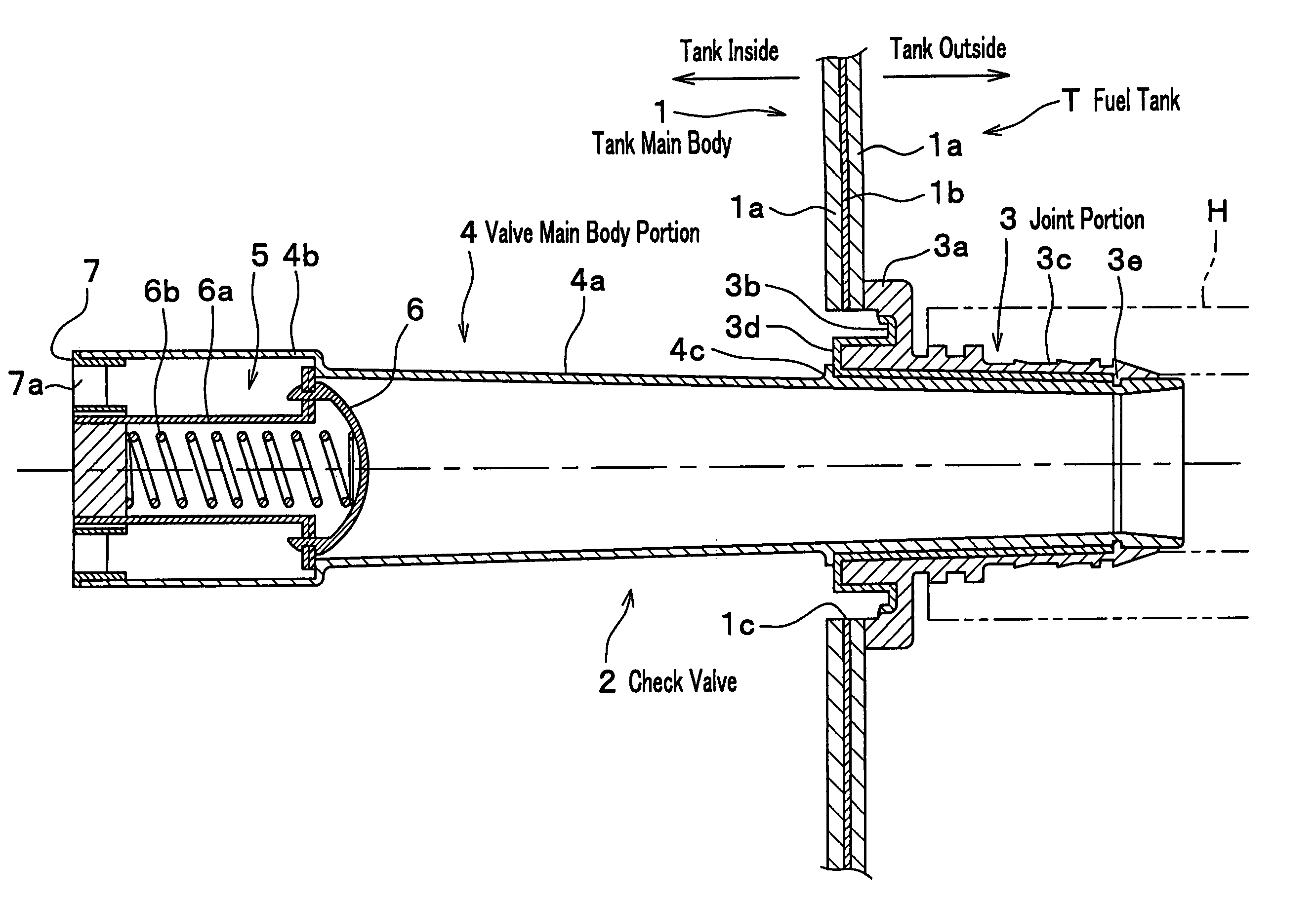
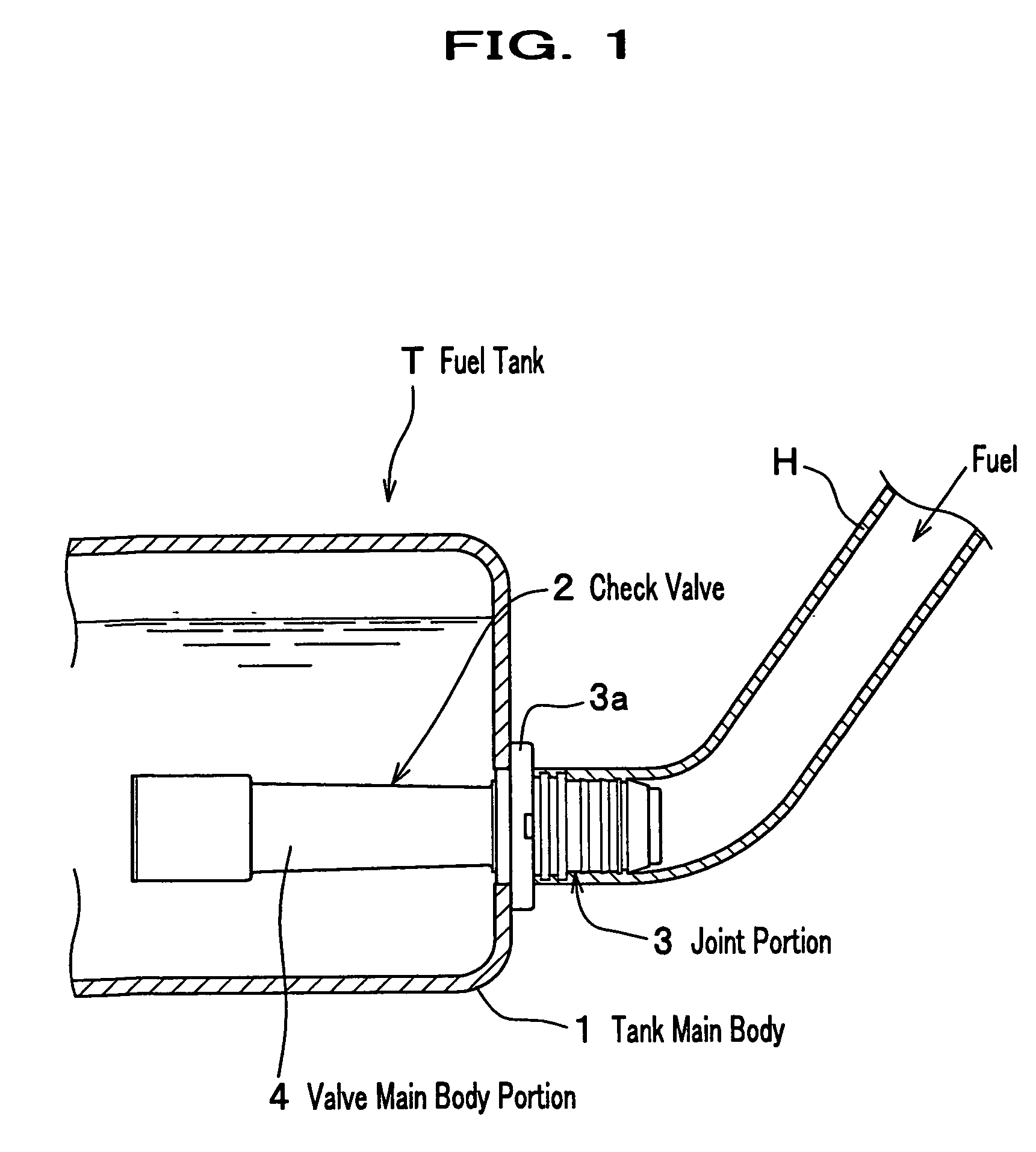
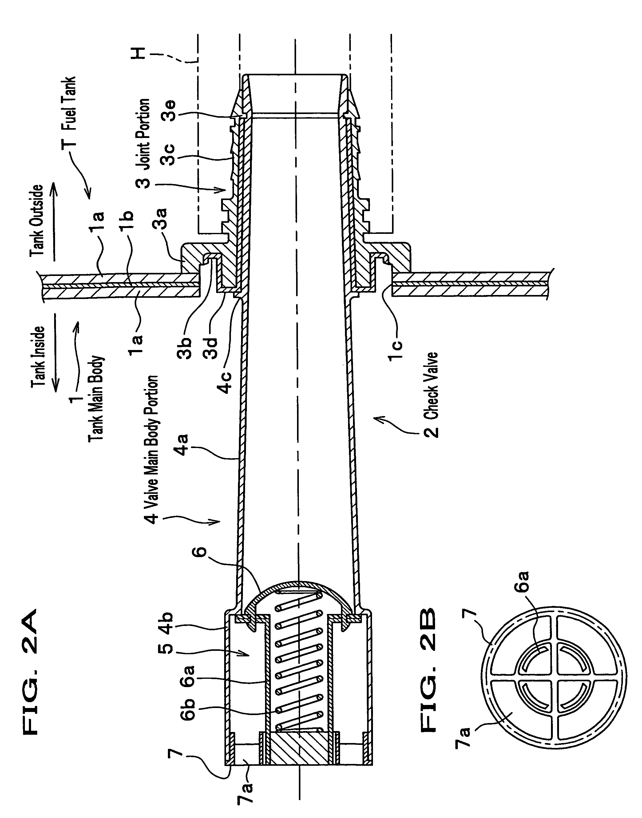
[0017]FIG. 1 is a section drawing showing an outline of an attachment structure of a component (check valve 2) related to an embodiment of the present invention. FIGS. 2A and 2B are enlargement drawings showing the check valve shown in FIG. 1; FIG. 2A is a section illustration; and FIG. 2B is a front view seen from a tank inside. In these drawings a fuel tank T comprises a tank main body 1 made of resin for reserving fuel, and to a side face of the tank main body 1 is attached the check valve 2 for preventing backflow of the fuel. The check valve 2 comprises a joint portion 3 attached to an outer peripheral edge portion of a through hole 1c formed on the side face of the tank main body 1, and an inner tubular member of a cylindrical form (valve main body portion 4) supported by the joint portion 3 and inserted (housed) inside the tank main body 1. The tank main body 1 is designed to be a section shape where, for example, an HC barrier layer 1b consisting of EVOH (ethylene-vinylalcoh...

second embodiment

[0025]Next will be described a second embodiment of the present invention. FIGS. 3A and 3B are enlargement section drawings illustrating a second embodiment. Meanwhile, in the second embodiment a same symbol is added for a same element as in the first embodiment, and a description thereof is omitted. A point of the second embodiment different from the first embodiment exists in a concrete form related to the movement regulation mechanism. Although the first embodiment is designed to be a mode that the annular protrusion 3e is provided so as to cut into the outer periphery of the tube middle portion 4a at the side of the tube connection pipe portion 3c and to bump the tube connection pipe portion 4c, which is annularly formed at the outer periphery of the tube middle portion 4a, to the end face 3d of the HC barrier material layer 3b fronting the inside of the tank main body 1, the second embodiment is designed to be a mode that a claw portion 4d like a hook is formed at an end portio...


PUM


Abstract

In order to solve the problem of a conventional attachment structure of a fuel tank made of resin, the present invention is an attachment structure of a component of a fuel tank made of resin where a connection portion with a tank main body made of resin is formed of a thermally depositable material, and which tank comprises a joint portion connected with the tank main body by a thermal deposition and an inner tubular member supported by the joint portion and housed in the tank main body, wherein a movement regulation mechanism for regulating a movement in an axial direction of the inner tubular member for the joint portion is provided at least at one of the joint portion and the inner tubular member, and the joint portion and the inner tubular member are formed by an integral molding.

Description

BACKGROUND OF THE INVENTION[0001]1. Field of the Invention[0002]The present invention relates to a fuel tank made of resin mounted on an automobile and the like.[0003]2. Description of the Related Art[0004]In a fuel tank mounted on an automobile a tank made of resin by a blow molding in these years becomes a main flow from a viewpoint such as anti-rust and weight saving. Usually, to the fuel tank are attached various components such as a vent valve for leading out a fuel-vapor gas in a space over a liquid surface out of the tank and keeping a tank inside pressure constant, a check valve connected to a filler tube, and a fuel pump; and in a case of a fuel tank made of resin it is desirable that the components are connected with a tank main body by a thermal deposition from a viewpoint of a simplification of a manufacturing process.[0005]FIG. 4 is a partial section drawing showing an attachment structure of a component in a conventional fuel tank made of resin. A symbol 24 shows a tan...

Claims


Application Information

Patent Timeline
IPC IPC(8): F17D1/00F16K21/04
CPCF16K15/026B29L2031/7172Y10T137/7933Y10T137/86372
Inventor YOSHIZAWA, YUUJIMATUZAKI, TOHRUMURABAYASHI, SHINYAKANEKO, NAOMASAISAYAMA, AKIRANAKAMURA, TADAHISANAKAI, TOSHIAKIKOSEKI, JUNICHIYAMAMOTO, SHOHEI
Owner YACHIYO IND CO LTD
Why Eureka
Try Eureka