Seal member, liquid discharge head having the same, and liquid discharge apparatus

a liquid discharge head and seal member technology, applied in mechanical devices, engine seals, printing, etc., can solve the problems of liquid leakage, clogging of flow channels, misalignment of communicating holes of seal members, etc., and achieve the effect of improving reliability

Active Publication Date: 2016-09-06
SEIKO EPSON CORP
View PDF10 Cites 1 Cited by
  • Summary
  • Abstract
  • Description
  • Claims
  • Application Information

AI Technical Summary

Benefits of technology

[0011]According to the invention, a dimensional change of the seal member as a whole is reduced irrespective of the type of the used liquid (the liquid passing through the communicating holes), which ensures the sealing properties further reliably. In other words, even though the plasticizer contained in the material of the elastic portion is lost gradually due to contact with the liquid, the plasticizer is replaced by the ink or the like. In addition, since a periphery of the elastic portion is surrounded by the main body portion having high liquid-resistant properties, the replaced liquid is unlikely to be volatilized from the elastic portion. Even though the liquid contained in the elastic portion is volatilized, since the periphery of the elastic portion is surrounded by the main body portion, the dimensional change of the elastic portion is restricted. Therefore, an occurrence of misalignment of the communicating holes with respect to the first flow channel and the second flow channel is prevented. Consequently, the sealing properties between the flow channels may be enhanced irrespective of the type of the used liquid.Means 2
[0023]In this configuration, by fitting the mount reference portion into the void portion and inserting the positioning pin into the reference hole, the seal member is arranged at a correct position in a correct orientation between the first member and the second member. Accordingly, efficiency of a mounting operation is improved.Means 8
[0032]According to the configuration of Means 11 and Means 12, since the seal member having a configuration in which the dimensional change is reduced irrespective of the type of the used liquid and the sealing properties are reliably secured, an improvement of reliability is achieved.

Problems solved by technology

Consequently, the ink or the like penetrated in the seal member volatilizes, for example, when exposed to a high-temperature and dry environment, and dimensions of the seal member is contracted as a whole, which could lead to misalignment of communicating holes of the seal member with respect to the flow channels to be sealed.
As a result, flow channels may be clogged, or liquid may leak due to an impairment of sealing properties.

Method used


Image

  • Seal member, liquid discharge head having the same, and liquid discharge apparatus
  • Seal member, liquid discharge head having the same, and liquid discharge apparatus
  • Seal member, liquid discharge head having the same, and liquid discharge apparatus

Examples


Embodiment Construction

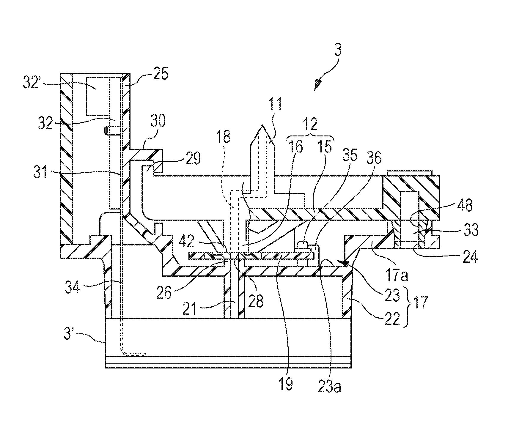
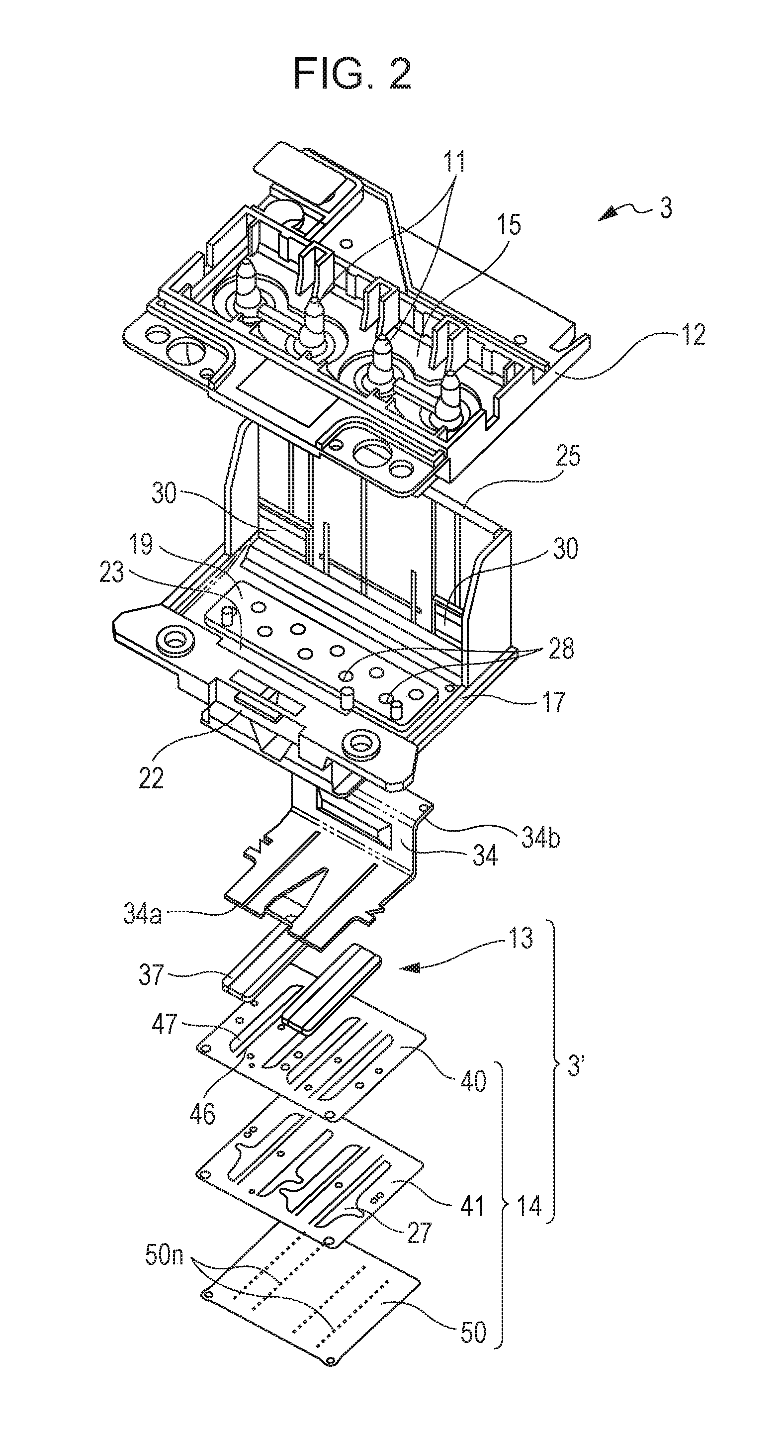
[0045]Hereinafter, embodiments of the invention will be described with reference to the attached drawings. In the embodiments described below, various definitions are made as preferred specific examples of the invention. However, the scope of the invention is not limited to those examples unless otherwise specifically described. In the following description, an example in which the invention is applied to a seal member 19 configured to seal a flow channel of an ink jet recording head (hereinafter, referred to simply as a recording head 3), which is a type of a liquid discharge head will be exemplified.

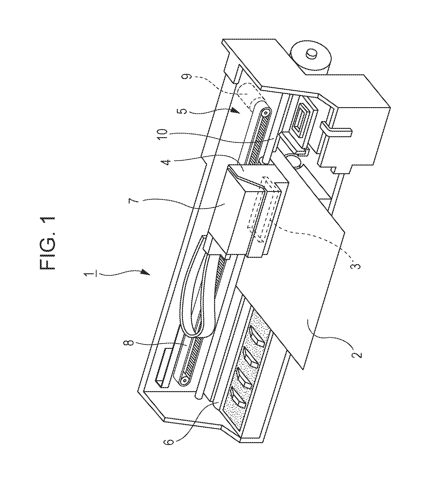
[0046]Firstly, a configuration of a printer 1, which is a type of a liquid discharge apparatus, will be described with reference to FIG. 1. The printer 1 is an apparatus configured to record images or the like by discharging liquid-state ink onto a surface of a recording medium 2 such as a recording sheet or a film. The printer 1 is provided with a recording head 3, a carriage 4 on whi...


PUM


Abstract

A seal member to be arranged between a first member having a first flow channel and a second member having a second flow channel, including: an elastic portion formed of an elastically deformable first material and including at least a communicating portion provided with a communicating hole which communicates a first flow channel and a second flow channel; and a main body portion formed of a second material having higher liquid-resistant properties than the first material and configured to surround the elastic portion in a state in which at least a flow channel seal surface of the communicating portion is exposed.

Description

CROSS-REFERENCE TO RELATED APPLICATIONS[0001]This application claims priority to Japanese Patent Application No. 2014-250977 filed on Dec. 11, 2014. The entire disclosure of Japanese Patent Application No. 2014-250977 is hereby incorporated herein by reference.BACKGROUND[0002]1. Technical Field[0003]The present invention relates to a seal member configured to communicate flow channels in a liquid-tight manner, a liquid discharge head having the seal member, and a liquid discharge apparatus.[0004]2. Related Art[0005]Examples of a liquid discharge head include an ink jet recording head used for an image recording apparatus such as an ink jet recording apparatus. In recent years, however, the liquid discharge head is applied to various manufacturing apparatuses by making full use of such a feature that liquid of a very small amount can be landed accurately onto a predetermined position.[0006]For example, the liquid discharge head is applied to display manufacturing apparatuses configur...

Claims


Application Information

Patent Timeline
Patent Type & Authority Patents(United States)
IPC IPC(8): B41J2/165F16J15/02
CPCB41J2/165F16J15/021B41J2/01B41J2/14B41J2002/14467B41J2/1752B41J2/17523
Inventor HAGIWARA, HIROYUKIOWAKI, HIROSHIGE
Owner SEIKO EPSON CORP
Why Eureka
Try Eureka