

Optical laminate
- Summary
- Abstract
- Description
- Claims
- Application Information
AI Technical Summary
Benefits of technology
Problems solved by technology
Method used
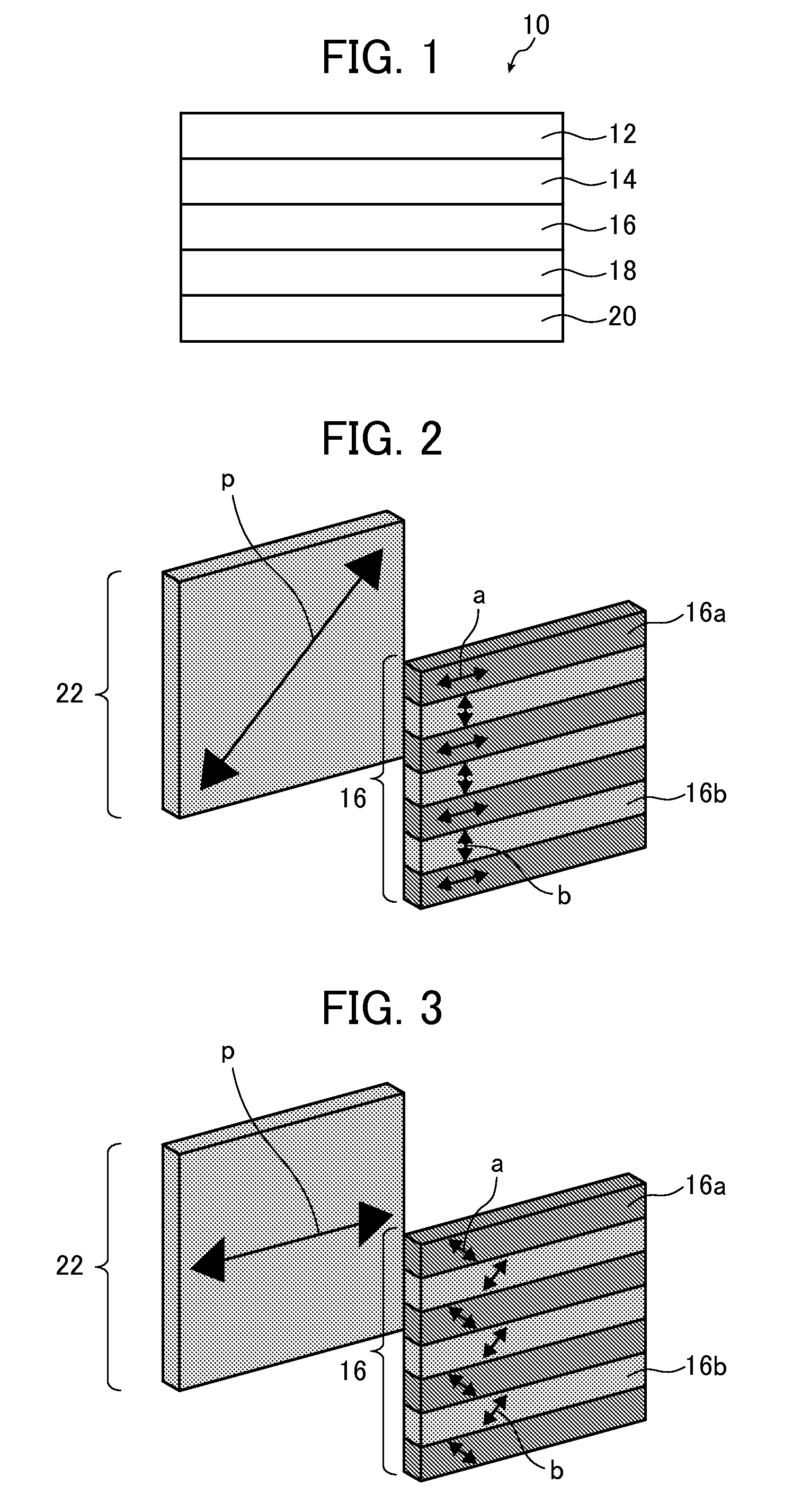
Image

Examples
example 1
Preparation of Transparent Support
[0148](Preparation of Cellulose Acylate Dope)
[0149]The following composition was put into a mixing tank and stirred such that the respective components were dissolved, thereby preparing a cellulose acylate solution.
[0150]In the makeup of the following components, the amount of the plasticizer and the ultraviolet absorber added is represented by “part by mass” with respect to 100 parts by mass of cellulose acylate (cellulose acetate having a degree of acetyl substitution of 2.88).
[0151](Makeup of Components)
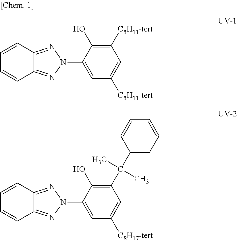
Plasticizer (P-1) 12 parts by massUltraviolet absorber (UV-1)1.8 parts by massUltraviolet absorber (UV-2)0.8 parts by mass
[0152]The makeup of the solvent is as follows. A cellulose acylate dope was prepared by adjusting concentration thereof such that the concentration of cellulose acetate became 17% by mass.
[0153](Makeup of Solvent)
Methylene chloride (a first solvent)92 parts by massMethanol (a second solvent) 8 parts by mass
[0154]Furthermore, t...
example 2
[0215]A transparent cellulose acetate support was prepared in the same manner as in Example 1, except that the thickness thereof was changed to 20 μm. By using the support, an optical laminate was prepared in the same manner as in Example 1.
example 3
[0216]A transparent cellulose acetate support was prepared in the same manner as in Example 1, except that the thickness thereof was changed to 25 μm. By using the support, an optical laminate was prepared in the same manner as in Example 1.
PUM
 Abstract
Description
Claims
Application Information