Cantilevered multi purpose tower and method for installing drilling equipment

a multi-purpose tower and installation method technology, applied in special purpose vessels, sealing/packing, borehole/well accessories, etc., can solve the problems of limiting the number of possible uses of the deck area, relative inaccessibility of the drill floor, and accidents of all sorts

Inactive Publication Date: 2006-08-01
ITREC BV
View PDF23 Cites 36 Cited by
  • Summary
  • Abstract
  • Description
  • Claims
  • Application Information

AI Technical Summary

Benefits of technology

[0002]The invention relates to a drilling rig for use in the offshore industry in the form of a Jack Up platform, Tension Leg, Compliant Tower, Mono Hull Ship or Semi-Submersible on which a cantilever is mounted so as to be movable at least in two directions, with the cantilever projecting more or less outside the drilling rig. On the cantilever a Multi Purpose Tower is present, which Multi Purpose Tower is moveable relative to the platform in a second direction, different from the first direction. This Multi Purpose Tower is fixedly mounted on the cantilever and preferably forms an integral part of the construction of the cantilever.

Problems solved by technology

Accidents of all sorts have occurred with the presence of the rails or three part housings on the deck of the jack up rig and other various other sorts of drilling rigs.
Furthermore these rails or housings considerably limit the number of possible uses of the deck areas on which the rails or housings are fixed.
Another disadvantage of a drilling derrick is the relative inaccessibility of the drill floor due to the large number of structural beams that are in the way.
This severely limits the possible number of useful activities that can be carried out on the drill floor and consequently the number of useful activities that a drilling rig can perform.
As a consequence, the drilling pattern is limited to drillings within a small rectangular shape.
A further drawback of the conventional rigs is that between drilling rig and cantilever, as well as between cantilever and drilling derrick, flexible connections should be provided for pipes, cable work, etc.

Method used


Image

  • Cantilevered multi purpose tower and method for installing drilling equipment
  • Cantilevered multi purpose tower and method for installing drilling equipment
  • Cantilevered multi purpose tower and method for installing drilling equipment

Examples


Embodiment Construction

[0043]Before explaining the present invention in detail, it is to be understood that the invention is not limited to the particular embodiments and that it can be practiced or carried out in various ways.

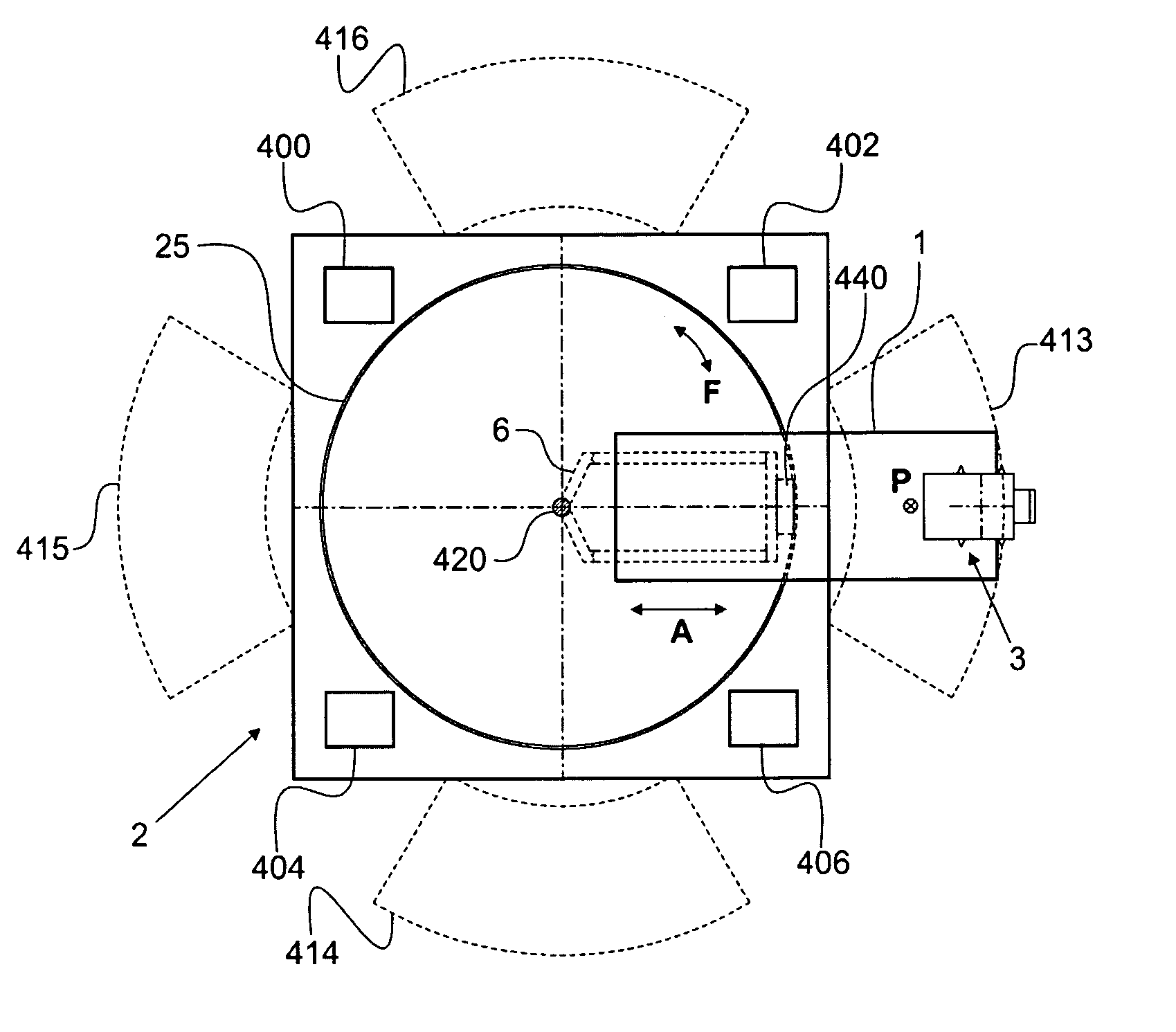
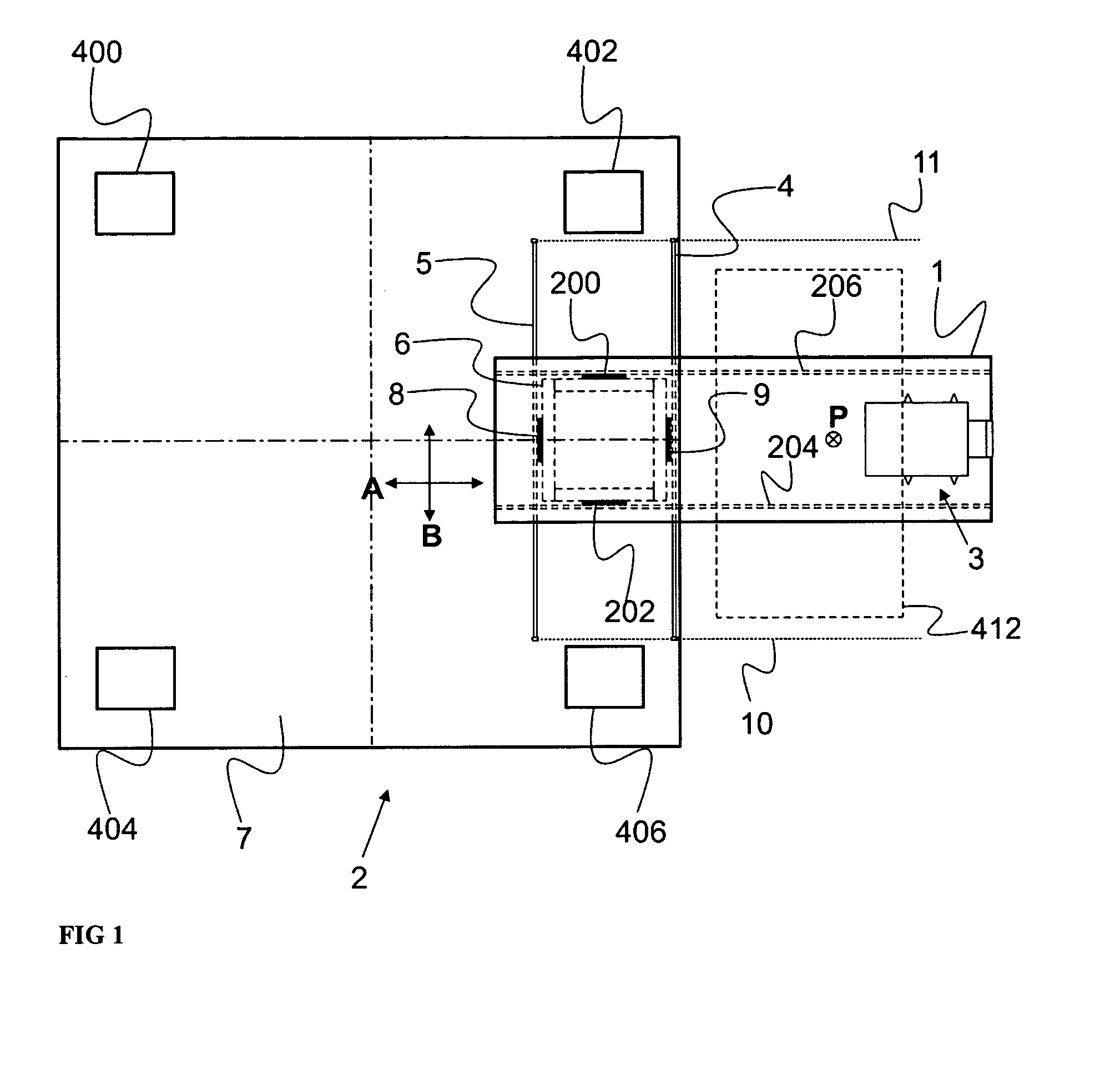
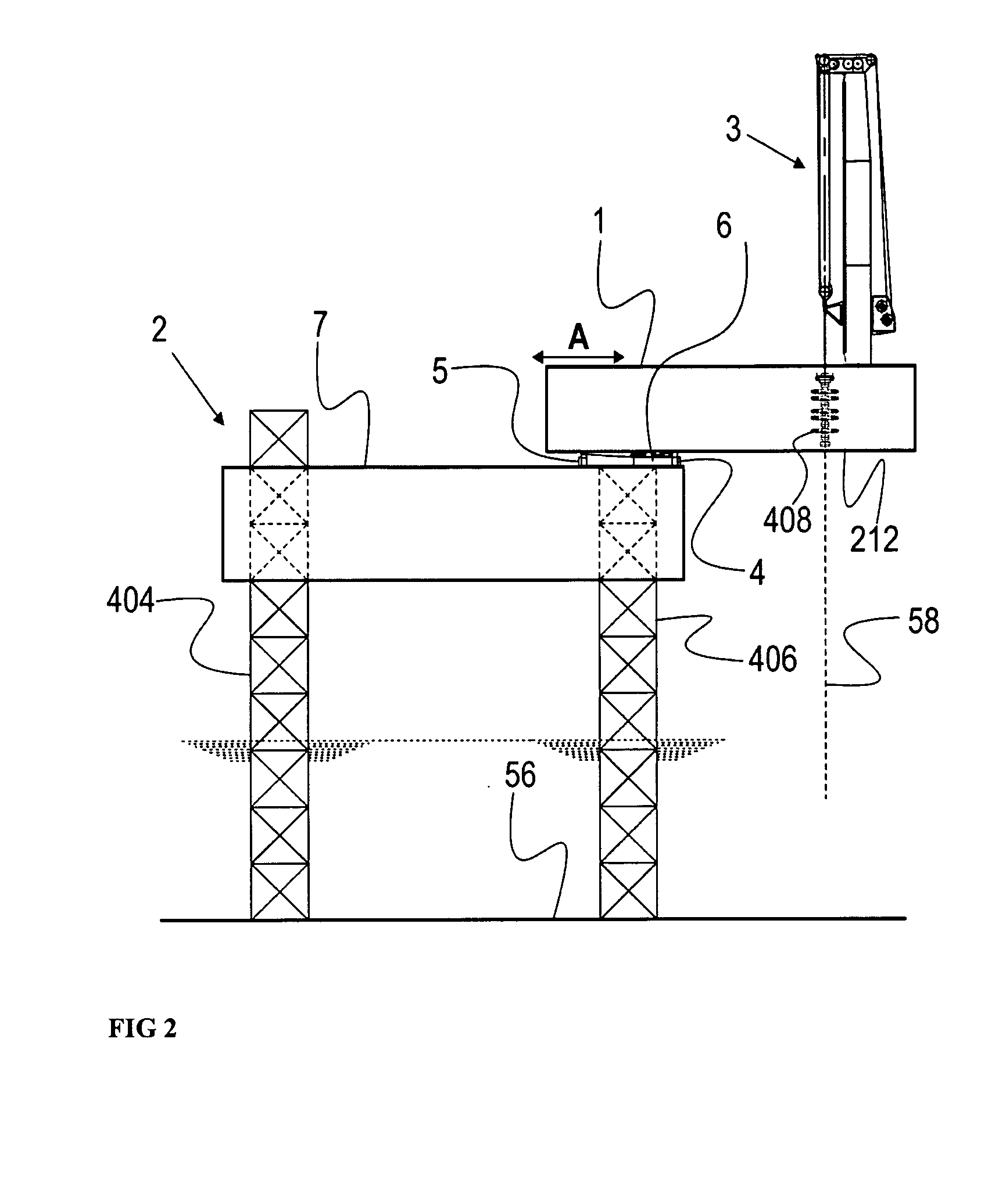
[0044]The invention relates to methods for drilling of, performing work-overs on, and providing maintenance for sub sea wells using a moveable and / or rotating-cantilevered Multi Purpose Tower.

[0045]Also the object of the invention is to provide a drilling rig wherein the earlier mentioned drawbacks are avoided at least to a considerable extent. To this end, according to the invention, the drilling rig as described in the opening paragraph is characterized in that the drilling tower is fixedly mounted on the cantilever and the cantilever is movable relative to the drilling rig.

[0046]As a result, the drilling point always remains in the same place relative to the cantilever, viz. preferably centrally between the two cantilever side walls. This leads to a symmetric load on the cantilev...


PUM


Abstract

A drilling rig having a deck capable of being used offshore and a method for commissioning a well using the drilling rig and a method for decommissioning a well using the drilling rig, wherein the drilling rig comprises: a cantilever which is mounted so as to be moveable in a first direction and a second direction; a Multi Purpose Tower mounted on the cantilever; a supporting cart disposed between the cantilever and the deck which in turn is movably fixed on the deck of the drilling rig; at least two friction reducing devices attached to the supporting cart; and wherein the cantilever can slide relative to the drilling platform.

Description

CROSS REFERENCE TO RELATED APPLICATIONS[0001]This application claims priority to U.S. patent application Ser. No. 60 / 419,128, filed Oct. 17, 2002 and U.S. patent application Ser. No. 10 / 225,770, filed Aug. 22, 2002, Pat. No. 6,729,804, issued 4 May 2004 both of which are incorporated herein.FIELD OF THE INVENTION[0002]The invention relates to a drilling rig for use in the offshore industry in the form of a Jack Up platform, Tension Leg, Compliant Tower, Mono Hull Ship or Semi-Submersible on which a cantilever is mounted so as to be movable at least in two directions, with the cantilever projecting more or less outside the drilling rig. On the cantilever a Multi Purpose Tower is present, which Multi Purpose Tower is moveable relative to the platform in a second direction, different from the first direction. This Multi Purpose Tower is fixedly mounted on the cantilever and preferably forms an integral part of the construction of the cantilever.BACKGROUND OF THE INVENTION[0003]Drilling...

Claims


Application Information

Patent Timeline
Patent Type & Authority Patents(United States)
IPC IPC(8): E21B15/02B63B35/44E02B17/00E21B15/00
CPCE02B17/021E21B19/146E21B15/003B63B35/4413E02B2017/006
Inventor ROODENBURG, JOOPVAN DUIVENDIJK, PIETER DIRK MELIS
Owner ITREC BV
Why Eureka
Try Eureka