Massage apparatus and method for lumbar support

a technology of lumbar support and massage apparatus, which is applied in the direction of roller massage, movable seats, chairs, etc., can solve the problem that the size and power of the actuators and motors required to move the present pressure surface with molded surface variations is not as grea

Inactive Publication Date: 2006-08-01
L & P PROPERTY MANAGEMENT CO
View PDF65 Cites 27 Cited by
  • Summary
  • Abstract
  • Description
  • Claims
  • Application Information

AI Technical Summary

Benefits of technology

[0015]The present invention is a massaging ergonomic support, such as lumbar support, that is smaller, thinner, lighter and more economical than prior art massaging lumbar supports. The present invention imparts the tactile effect of massaging, but without rollers. It does so by using an active portion or pressure surface that has integral undulations, corrugations or bumps on it, rather than being smooth. These surface variations may be imparted to the pressure surface of the active portion through molding in plastic or stamping in metal.
[0016]The massage lumbar support of the present invention further reduces size, weight and expense by eliminating the need for actuators to be directly mounted to the static portion of the ergonomic support. In the present invention, actuator gearboxes and motors are connected to the static and / or active portions of the lumbar support only by the actuating linkage, such as a Bowden cable. The weight and size of the mounting brackets is thereby saved. Instead, the actuators are capable of being mounted directly on any seat-frame. Accordingly, the added advantage of being readily customizable for mounting in any seat-frame is gained. Moreover, the size and power of the actuators and motors required to move the present pressure surface with molded surface variations is not as great as that required for prior art massaging lumbar supports.

Problems solved by technology

Moreover, the size and power of the actuators and motors required to move the present pressure surface with molded surface variations is not as great as that required for prior art massaging lumbar supports.

Method used


Image

  • Massage apparatus and method for lumbar support
  • Massage apparatus and method for lumbar support
  • Massage apparatus and method for lumbar support

Examples


Embodiment Construction

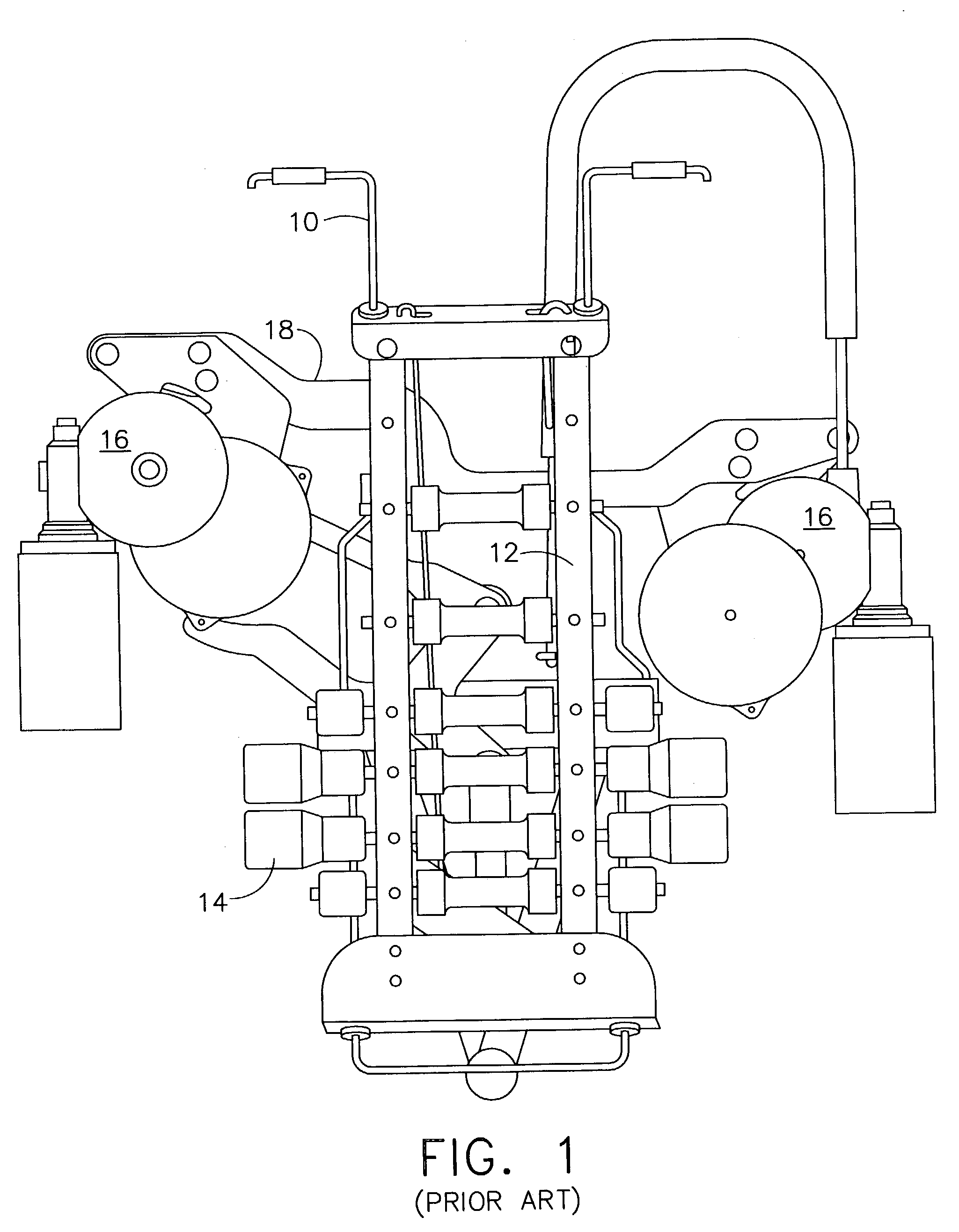
[0025]Referring to the accompanying drawings in which like reference numbers indicate like elements, FIG. 1 illustrates a prior art massaging lumbar support. The prior art support has a static portion 10. In the depicted embodiment this is a pair of guide rails. An active portion 12 is an arching pressure surface. The arching pressure surface of the prior art supports an array of rollers 14. Actuators 16 move the active portion 12 up and down and in and out. One or both of the prior art actuators 16 were held onto the static portion 10 by brackets 18.

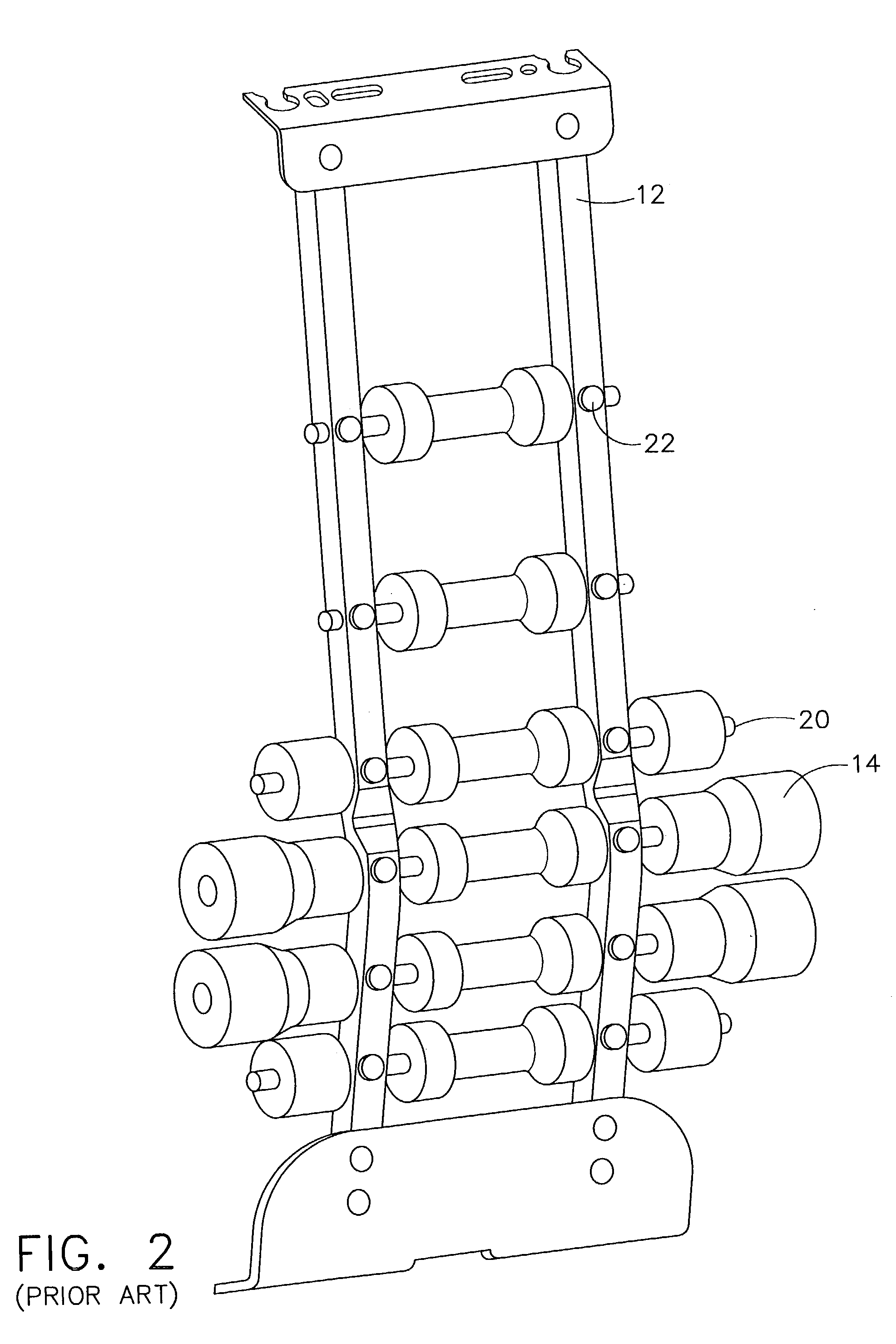
[0026]FIG. 2 is a perspective view of an arching pressure surface for a prior art massaging lumbar support. As can be seen, the arching pressure surface 12 supported an array of rollers 14. Each of the rollers 14 had to be supported by an axle or pin 20. The axles and pins had to be fixated to the arching pressure surface 12 by rivets, welds or the like 22. This structure is heavy, complex, expensive and cumbersome. This size, weight an...


PUM


Abstract

An ergonomic support mountable on various seat frames has a static portion with anchors and mounts. The mounts adapt to fix said static portion to varying seat frames. An active portion is operatively engaged with the anchors of the static portion such that the active portion can move in and out of a plane defined by the frame of the seat. The active portion has a pressure surface with a smooth base level. There are convexities in the base level that impart a massage effect on a seat occupant. At least one actuator engages the active portion but only by an actuating linkage.

Description

CROSS-REFERENCE TO RELATED APPLICATIONS[0001]None.STATEMENT REGARDING FEDERALLY SPONSORED RESEARCH OR DEVELOPMENT.[0002]Not Applicable.APPENDIX.[0003]Not Applicable.BACKGROUND OF THE INVENTION[0004]1. Field of the Invention[0005]The present invention is in the field of ergonomic supports for seats, especially automobile seats.[0006]2. Prior Art[0007]Ergonomic supports for seats, especially automobile seats that impart a massage type effect on the seat occupant, are known in the art. See, e.g., U.S. patent application Ser. No. 09 / 536,425, incorporated by reference herein. Typically such prior art massage systems involve an active portion which moves toward and away from a portion of the seat occupant's anatomy to be supported, for example the lumbar spine. The active portion includes a surface that can be put into a variety of selectable positions supporting the spine to a greater or lesser degree. The moving or active portion of the lumbar support is typically a bowing or arching su...

Claims


Application Information

Patent Timeline
Patent Type & Authority Patents(United States)
IPC IPC(8): B60N2/66A47C7/46A61H1/00A61H15/00B60N2/02B60N2/90
CPCA61H15/0078B60N2/66B60N2/0232B60N2/448A61H2201/0138A61H2201/0149A61H2205/081B60N2/666B60N2/6673B60N2/976B60N2/6671B60N2/02246A61H39/04
Inventor FRANK, RICHARD
Owner L & P PROPERTY MANAGEMENT CO
Why Eureka
Try Eureka