Switch device having rubber dome and generating superior click feeling

a technology of a switch and a rubber dome, which is applied in the direction of contacts, contact surface shape/structure, electrical equipment, etc., can solve the problems of difficult to correspond to various application force of the switch, and achieve the effect of clear click feeling, less dimension, and simplified structur

Active Publication Date: 2006-08-01
ALPS ALPINE CO LTD
View PDF10 Cites 21 Cited by
  • Summary
  • Abstract
  • Description
  • Claims
  • Application Information

AI Technical Summary

Benefits of technology

[0014]In the invention, since the outer periphery of the base to be affected by pressing the rubber dome for small application force is prevented from unnecessarily bending by the base of the rubber dome for heavy application force and the preventing part, the rubber dome for small application force is normally buckling, so that clear click feelings can be obtained. Further, since the base of the rubber dome for heavy application force can replace the preventing part, the preventing part for deformation does not need to be separately disposed in the base, which makes it possible to lessen the dimensions and even to simplify the structure. Further, since deformation can be prevented by using the switch case having high rigidity, in a region where the base around the rubber dome for heavy application force cannot be used as a preventing part for deformation, the switch case can be made smaller, compared to the switch case having the preventing part disposed in the click rubber.
[0016]In this way, it is possible to make smaller and simpler switches for small application force and heavy application force, and generate clear click feelings.
[0018]In the invention, when heavily pressing the click rubber so as to prevent deformation, the amount of deformation of the base depends on differences of pressed loads on the base, which may cause different click feelings. However, since the preventing part is in contact with the internal wall face of the switch case and the side of the base, the amount of deformation of the base never changes, thereby ensuring stable click feelings.

Problems solved by technology

However, since the rubber domes 119 have the same shape, it is very difficult for the rubber domes to correspond to various application force.

Method used


Image

  • Switch device having rubber dome and generating superior click feeling
  • Switch device having rubber dome and generating superior click feeling
  • Switch device having rubber dome and generating superior click feeling

Examples


Embodiment Construction

[0031]Hereinafter, a preferred embodiment of the present invention will now be described with reference to the drawings.

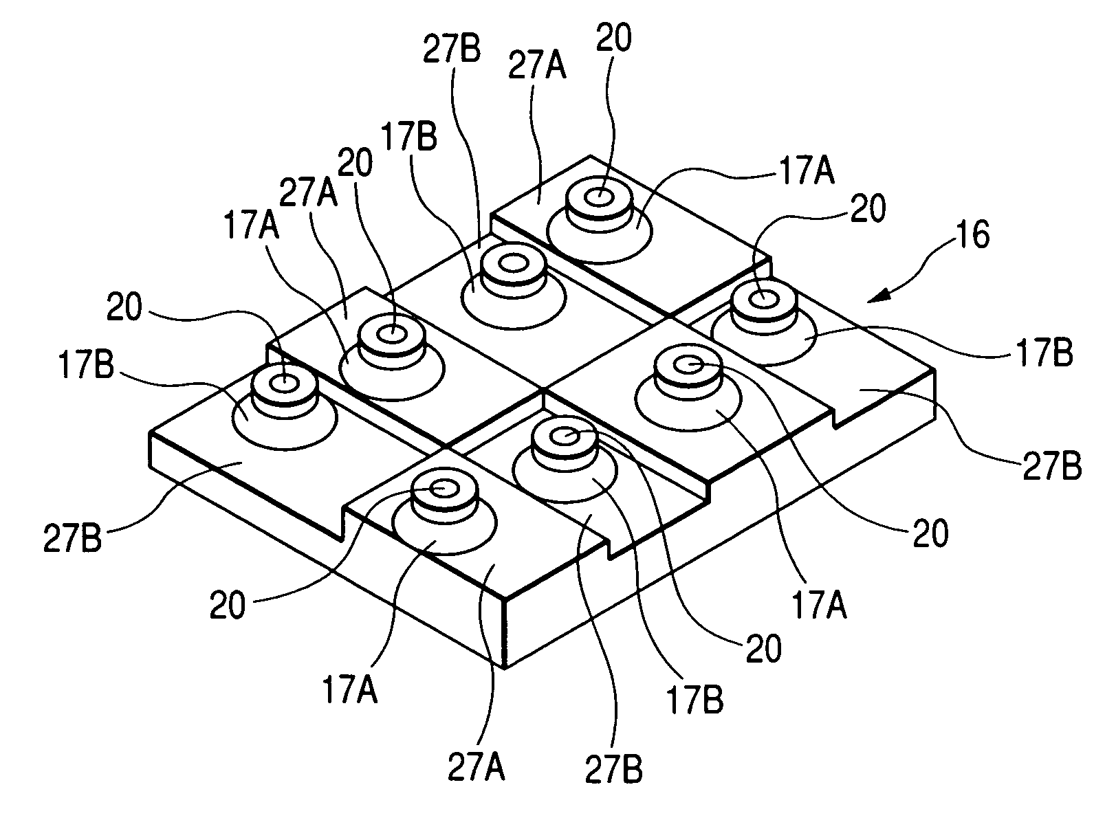
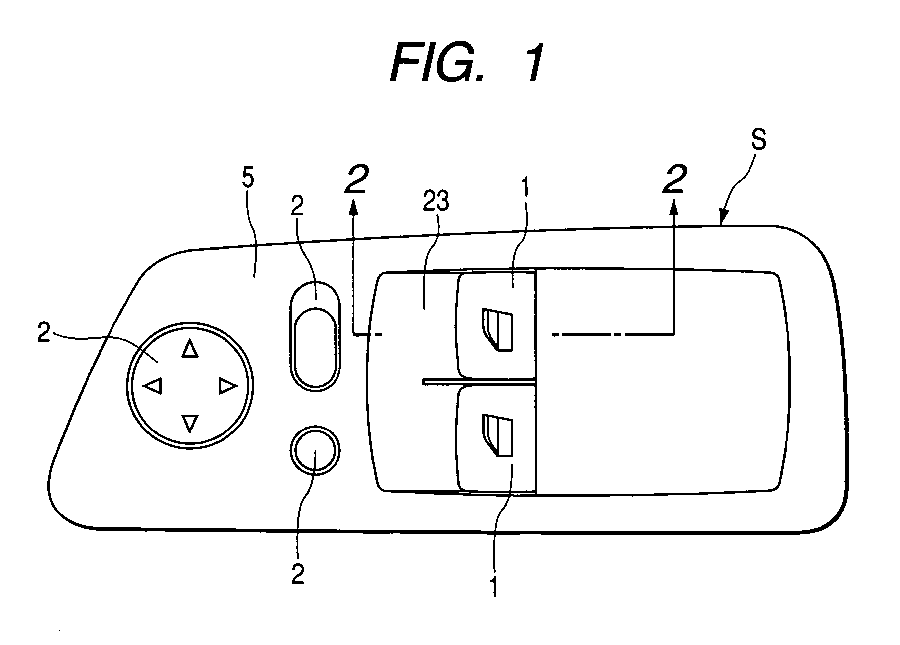
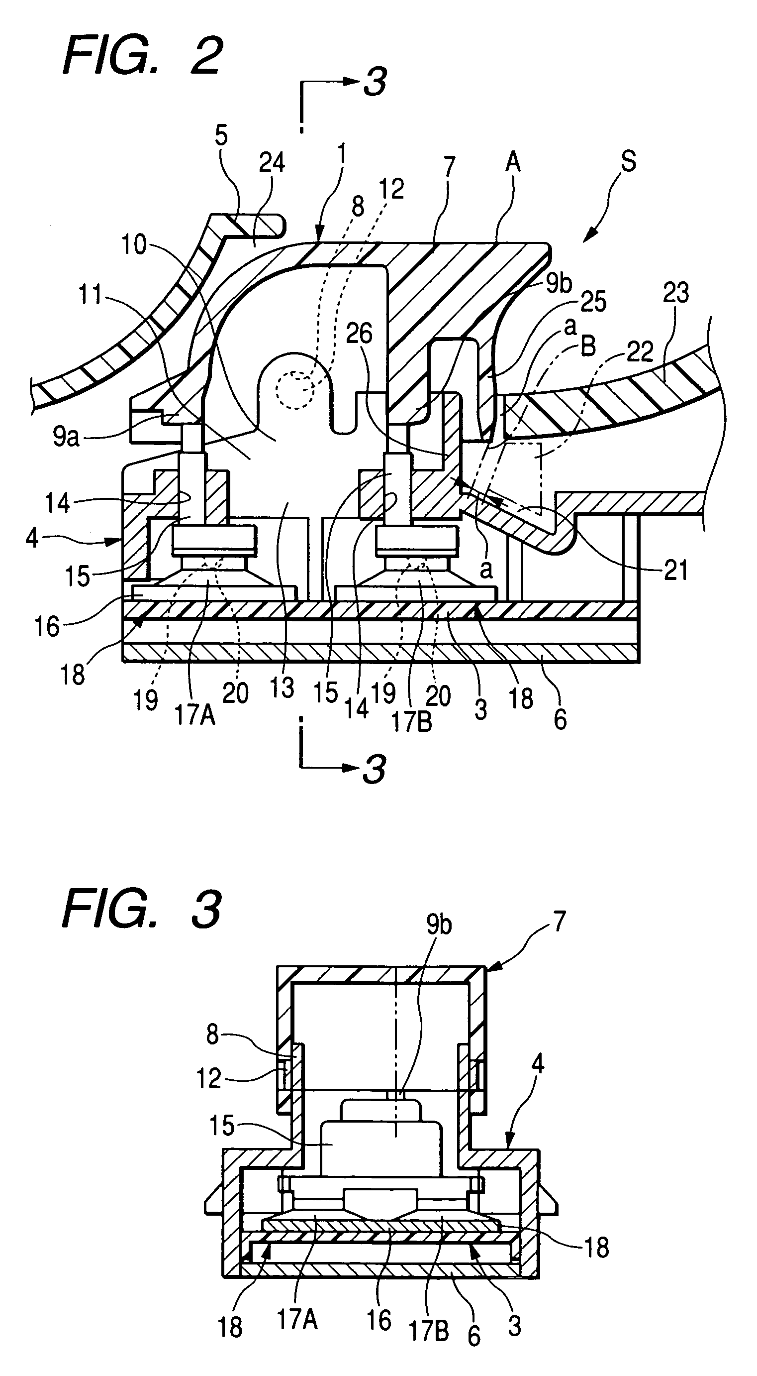
[0032]FIG. 1 is a plan view of a power window switch device to which a switch device according to the embodiment of the invention is applied; FIG. 2 is a cross-sectional view of the power window switch device taken from the line 2—2 of FIG. 1; FIG. 3 is a cross-sectional view of the power window switch device taken from the line 3—3 of FIG. 1; FIG. 4 is a cross-sectional view showing a state in which the power window switch device is pressed; FIG. 5 is a cross-sectional view of the power window switch device taken from the line 5—5 of FIG. 4; FIG. 6 is a cross-sectional view showing a state in which the power window switch device is further pressed; FIG. 7 is a cross-sectional view of the power window switch device taken from the line 7—7 of FIG. 6; FIG. 8 is a cross-sectional view of a click rubber accommodated in a switch case; FIG. 9 is a perspective view of the...


PUM


Abstract

A switch device is provided with a first rubber dome for small application force, a second rubber dome for heavy application force, and an operation body. The rubber domes are integrally formed with a plate shaped base, and adjacent to each other. Lower ends of the operation body is disposed on the top surface of the first and second rubber domes. The operation body is movably supported in a vertical direction. The base around the second rubber dome is formed with a smaller thickness than the base around the first rubber dome. A preventing part is provided so as to prevent the base of the first rubber dome from deforming. The thick base around the second rubber dome for and the preventing part are disposed around an outer periphery of the base of the first rubber dome.

Description

BACKGROUND OF THE INVENTION[0001]1. Field of the Invention[0002]The present invention relates to a switch device for use as a power window switch of, for example, an automobile.[0003]2. Description of the Related Art[0004]As an example of a switch device in the related art, JP-A-2002-334631 discloses a power window switch of an automobile, and FIGS. 11 and 12 show the above power window switch.[0005]When a pulling operation is performed on a switch device S2 shown in FIG. 11 by hooking a finger on an operation side wall of a seesaw knob 101 so as to be pulled in an arrow direction indicated by C, the operation side wall 102 of the seesaw knob 101 is pulled, and then a driving member 103 integrally mounted on the seesaw knob 101 moves so as to pivot on a concavity 104 as a fulcrum, thereby pressing a switch operation part 105.[0006]When the switch operation part 105 is pressed, an operation body 106 in contact with the switch operation part 105 and a cam member 108 in contact with a ...

Claims


Application Information

Patent Timeline
Patent Type & Authority Patents(United States)
IPC IPC(8): H01H9/00H01H1/10
CPCH01H23/003H01H2300/01H01H2215/004
Inventor KONNO, SATORU
Owner ALPS ALPINE CO LTD
Why Eureka
Try Eureka