Push button structure with curved lever

a push button and lever technology, applied in the field of push button structure, can solve the problems of low yield rate, low sensitivity, compromising durability, etc., and achieve the effect of increasing the yield ra

Active Publication Date: 2013-10-01
D-LINK
View PDF6 Cites 3 Cited by
  • Summary
  • Abstract
  • Description
  • Claims
  • Application Information

AI Technical Summary

Benefits of technology

[0009]In view of the drawbacks of the conventional push button structures, the inventor of the present invention conducted extensive research and tests and finally succeeded in developing a push button structure with a curved lever as disclosed herein. The disclosed push button structure is intended to prevent uneven injection of molten plastic during the injection molding process so as to increase yield rate. It is also intended that the disclosed push button structure, when pressed, gives the user a clear feel of its being pressed.
[0010]It is an object of the present invention to provide a push button structure with a curved lever, wherein the push button structure includes a casing and a button body that are integrally formed by injection molding. The casing has an opening that extends through the surface of the casing. The button body is formed within the opening and has an outer periphery spaced from the inner periphery of the opening. In addition, the button body has an outer surface exposed on the surface of the casing and an inner surface extended by the curved lever, wherein the curved lever has a U-shaped, V-shaped, or other curved cross section. The curved lever has one end fixedly connected to an inner wall of the casing at a position adjacent to the opening such that the button body is movably positioned inside the opening. When the outer surface of the button body is pressed, the elasticity of the curved lever allows the button body to move toward the inside of the casing and thereby trigger an electronic switch in the casing. Once the pressing force is removed, the button body returns to its original position due to the elasticity of the curved lever. As the curved lever has a relatively long displacement path and relatively high elasticity, the user pressing the button body will have a clear feel of the button body's being pressed. Thus, incorrect operations of the push button structure (e.g., failure to trigger the electronic switch and triggering the electronic switch by accident) are prevented. Furthermore, due to its curved configuration, the curved lever can have its length and thickness easily adjusted to form the desired displacement path and produce the desired elasticity, so as for the button body, when pressed, to give a clear feel of its being so, thereby meeting the needs of most users. Moreover, the end of the curved lever that is adjacent to the button body will not bend at a large angle (e.g., 30˜50 degrees) when subjected to a pressing force; hence, the curved lever not only can sustain a relatively large pressing force, but also can be reasonably elastic even with an increased thickness. The curved lever is effective is enhancing the durability of the push button structure as well as solving the problem of uneven formation of the push button structure during the injection molding process.

Problems solved by technology

(1) Limitation in lever thickness: As the push button structure 1 depends on deformation of the lever 121 to enable movement of the button body 12 and thereby trigger the electronic switch, the lever 121 must not be too thick, or the elasticity of the lever 121 will be reduced, which prevents the deformation required for the button body 12 to be pressed against and trigger the electronic switch. In other words, an excessively thick lever 121 will lower the sensitivity of the push button structure 1. Therefore, while designing the push button structure 1, the thickness of the lever 121 must be controlled to ensure smooth operation of the push button structure 1.
(2) Limitation in lever length: Now that the lever 121 has its limitation in thickness as stated in the previous paragraph, the lever 121 must also not be too long; otherwise, when subjected to an undue pressing force, the end of the lever 121 that is adjacent to the button body 12 may bend at such a large angle (e.g., 30˜50 degrees) that the lever 121 is overloaded and breaks, thereby compromising the durability of the push button structure 1. Further, if the lever 12 is too long, the gap between the outer periphery of the button body 12 and the inner periphery of the opening 101 will be large and unsightly, and the lever 12 can be so floppy that the button body 12 is readily moved by the user's unintentional actions and thus triggers the electronic switch by accident, which is very inconvenient. In addition, if the lever 12 is too long, the button body 12 may tilt to one side when pressed and gives the user only a vague feel of its being pressed.
(3) Low yield rate: During the injection molding process of the push button structure 1, the cross section of the lever 121—which is under the aforementioned design limitations—tends to reduce the injection speed of molten plastic and therefore result in defects or a sink mark on button surface of the button body 12. In consequence, not only is the yield rate low, but also the production cost is increased.

Method used


Image

  • Push button structure with curved lever
  • Push button structure with curved lever
  • Push button structure with curved lever

Examples


Embodiment Construction

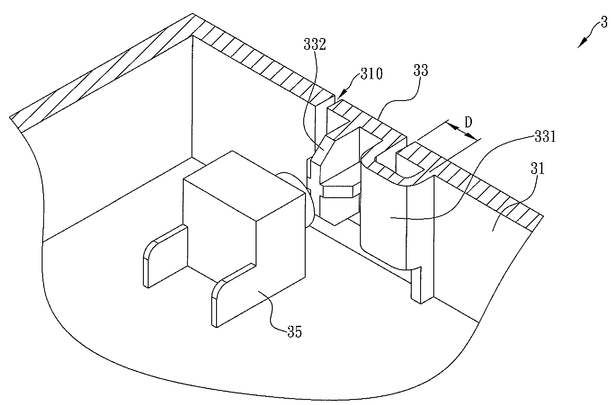
[0015]The present invention provides a push button structure with a curved lever. Referring to FIG. 3 for a preferred embodiment of the present invention, the push button structure 3 is applied to an electronic device (not shown) and includes a casing 31 and a button body 33. The casing 31 and the button body 33 are formed as a single unit by injection molding. In order to facilitate understanding of the technical features of the present invention, the upper right corner of FIG. 3 is defined as the outside of the casing 31 (and hence of the electronic device), and the lower left corner of FIG. 3 as the inside of the casing 31 (and hence of the electronic device).

[0016]As shown in FIG. 3, the casing 31 has an opening 310 that extends through the surface of the casing 31. The button body 33 corresponds in shape to the opening 310 and is formed within the opening 310. The outer surface of the button body 33 is exposed on the surface of the casing 31 so as to be pressed by the user. The...


PUM


Abstract

A push button structure includes a casing and a button body that are integrally formed by injection molding. The casing has an opening that extends through the surface of the casing. The button body is formed within the opening, and has an outer periphery spaced from the inner periphery of the opening and has an outer surface exposed on the surface of the casing and an inner surface extended by the curved lever. The curved lever has one end fixedly connected to an inner wall of the casing at a position adjacent to the opening such that the button body is movably positioned inside the opening. When the button body is pressed, the elasticity of the curved lever allows the button body to move toward the inside of the casing and thereby trigger an electronic switch in the casing.

Description

FIELD OF THE INVENTION[0001]The present invention relates to a push button structure, more particularly to a push button structure with a curved lever, so as to allow a user who presses a button body of the push button structure to have a clear feel of the movement of the button body and also enhance the durability of the push button structure as well as solving the problem of uneven formation of the push button structure existing in the prior art during an injection molding process.BACKGROUND OF THE INVENTION[0002]With the rapid development of technology, various electronic devices have become indispensable tools in our daily lives and work. These electronic devices provide assistance in a good number of fields such as information transfer, business transaction, interpersonal communication, document preparation, and computer graphics, so as to enable better and faster completion of certain tasks. Typically, the casing of such an electronic device is provided with a push button stru...

Claims


Application Information

Patent Timeline
Patent Type & Authority Patents(United States)
IPC IPC(8): H01H13/00
CPCG05G1/04H01H2221/074H01H2221/09
Inventor HUANG, CHENG-CHUN
Owner D-LINK
Why Eureka
Try Eureka