Wireless transmission evaluation system and method

a transmission evaluation system and wireless technology, applied in the direction of transmission monitoring, receiver monitoring, instruments, etc., can solve the problems of not being practicable or desirable to connect users of a communication network using physical links, such as wires, cables or fibre links

Inactive Publication Date: 2006-08-01
WSOU INVESTMENTS LLC
View PDF46 Cites 18 Cited by
  • Summary
  • Abstract
  • Description
  • Claims
  • Application Information

AI Technical Summary

Benefits of technology

[0014]In another broad aspect, a method of evaluating a tentative location for a fixed subscriber communication site of a wireless communication system using a wireless testing system is provided. The wireless testing system comprises a testing antenna for communicating wireless communication signals with a transmit antenna and a receive antenna at a base station, an adjustable mount associated with the testing antenna for orienting the testing antenna in a plurality of pan orientations and a plurality of tilt orientations, an adjustable boom attached to the adjustable mount for positioning the testing antenna at a plurality of heights, a signal measuring device associated with the testing antenna and a signal attenuator associated with the testing antenna. The method comprises, at the tentative location: a) positioning the testing antenna such that an angle α defined by the testing antenna as a vertex between the transmit and receive antenna is 1.5 degrees or less; b) adjusting tilt, pan, and height of the testing antenna to exchange wireless communication signals with the transmit and receive antennae; c) measuring a characteristic of the wireless communication signals received by the testing antenna by integrating a power signal of the wireless communication signals across a frequency band associated with the wireless communication signals; d) attenuating the wireless communication signals until the testing antenna no longer receives the wireless communication signals from the transmit antenna; e) calculating ambient atmospheric and meteorological conditions corresponding to the amo

Problems solved by technology

Occasionally, it is neither practical nor desirable to connect users of a com

Method used


Image

  • Wireless transmission evaluation system and method
  • Wireless transmission evaluation system and method
  • Wireless transmission evaluation system and method

Examples


Embodiment Construction

[0034]The description which follows, and the embodiments described therein, are provided by way of illustration of an example, or examples, of particular embodiments of the principles of the present invention. These examples are provided for the purposes of explanation, and not limitation, of those principles and of the invention. In the description which follows, like parts are marked throughout the specification and the drawings with the same respective reference numerals.

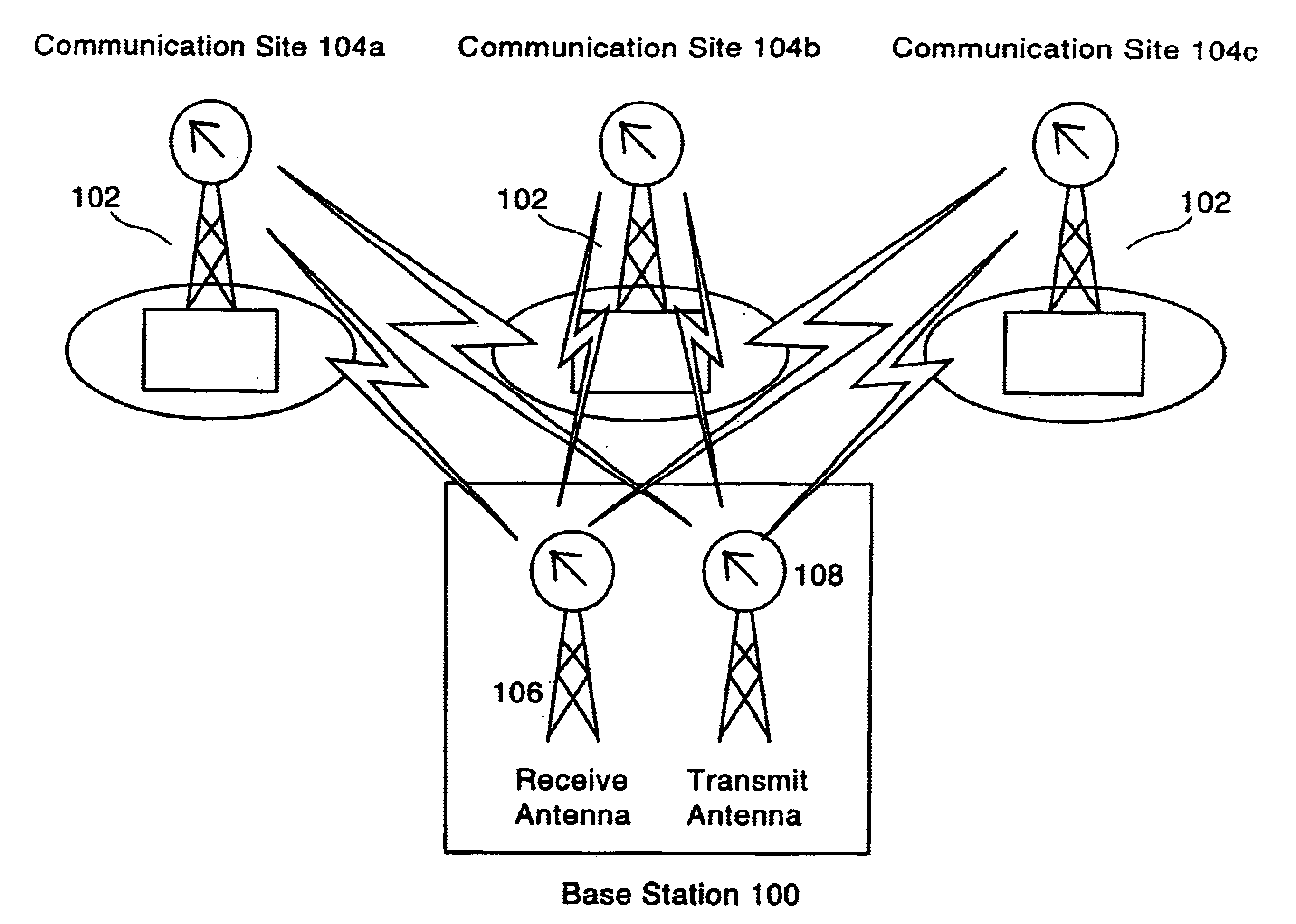
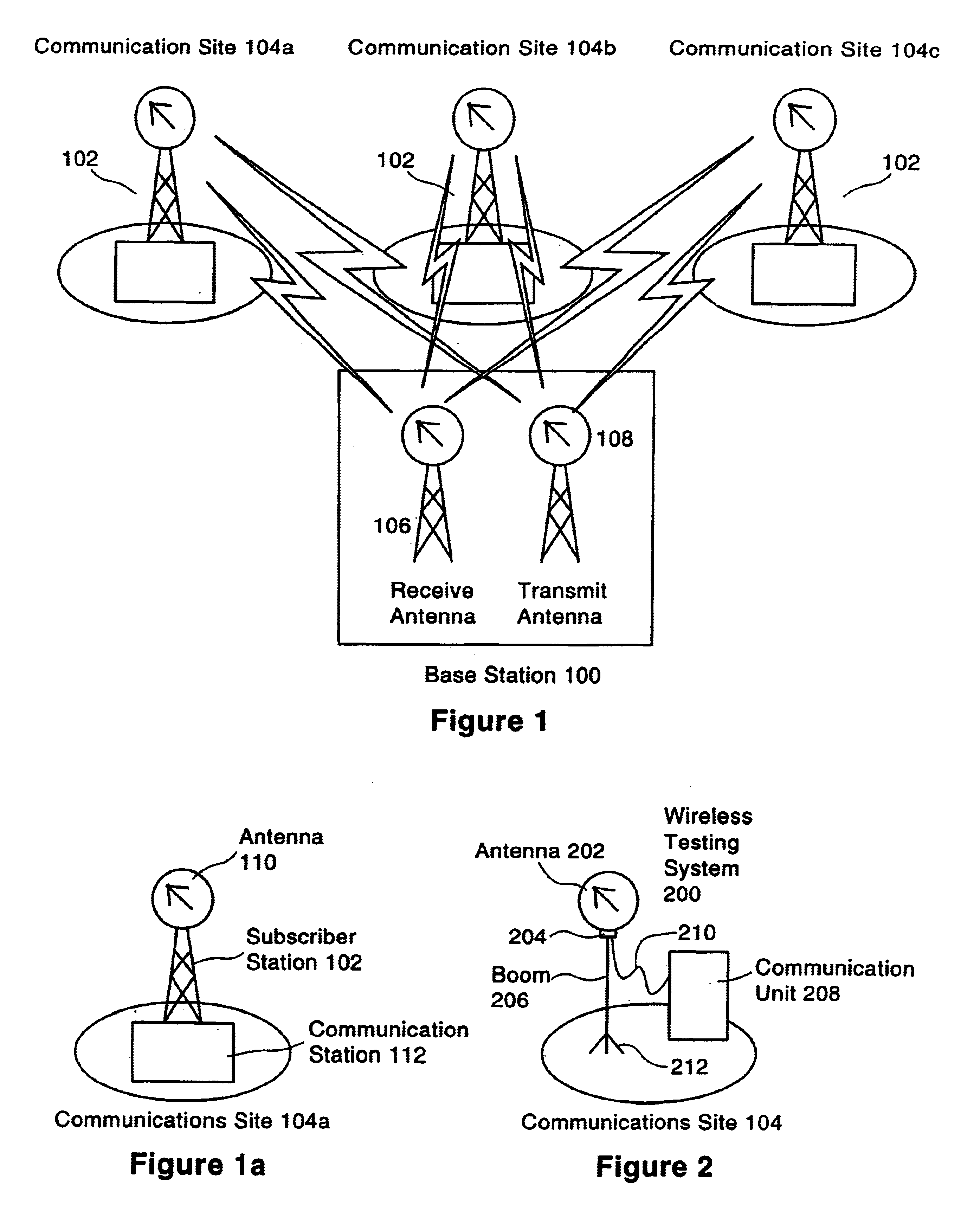
[0035]Referring to FIG. 1, wireless communication system 1 comprises base station 100 and a plurality of subscriber stations 102 at communication sites 104a, 104b and 104c. Each subscriber station 102 communicates with base station 100 via wireless communication signals. Base station 100 has a receive antenna 106 to receive wireless communication signals from subscriber stations 102 and a transmit antenna 108 to transmit wireless communication signals to subscriber stations 102. It can be appreciated that receive...


PUM


Abstract

A signal testing system and method for evaluating wireless communication signals transmitted between a base station and a communication site is provided. The signal testing system comprises an antenna located at the communication site for communicating the wireless communication signals between the base station and the communication site, an adjustable mount associated with the antenna for orienting the antenna in a plurality of pan orientations and a plurality of tilt orientations, an adjustable boom associated with the adjustable mount for positioning the antenna at a plurality of heights and a communication unit to measure characteristics of the wireless communication signals. The adjustable mount is fixed in a set pan orientation and a set tilt orientation and the adjustable boom is fixed height when the communication unit measures the characteristics of the wireless communication signals. The method uses the system.

Description

FIELD OF THE INVENTION[0001]The invention relates generally to a system and method to test a wireless communication site for wireless communications with a base station and more specifically to a system and method to measure characteristics of wireless communication signals using a portable, adjustable antenna system.BACKGROUND OF THE INVENTION[0002]Occasionally, it is neither practical nor desirable to connect users of a communication network using physical links, such as wires, cables or fibre links. Instead, a wireless communication network may be used to connect the communication network. In a typical wireless communication network, there is a base station communicating with subscriber stations. The base station typically has separate antennae for the receive and transmit functions.[0003]A user at a subscriber station communicates with the base station using a fixed antenna at the user's communication site. Often there are a number of potential locations for the communication si...

Claims


Application Information

Patent Timeline
IPC IPC(8): H04B1/38H04B17/00
CPCH01Q3/08H04B17/20H04B17/16
Inventor DAVIES, DOUGLAS ALLAN
Owner WSOU INVESTMENTS LLC
Why Eureka
Try Eureka