Subband domain signal validation

a subband domain and signal validation technology, applied in the field of process and machine modeling and system monitoring, can solve the problems of limiting the applicability of advanced techniques to equipment and processes instrumented with multiple sensors for correlated parameters and unsatisfactory operating conditions

Inactive Publication Date: 2006-08-01
UNIVERSITY OF CHICAGO
View PDF16 Cites 41 Cited by
  • Summary
  • Abstract
  • Description
  • Claims
  • Application Information

AI Technical Summary

Benefits of technology

[0009]The present invention achieves the above needs by means of a sub-band decomposition technique coupled with signal feature extraction for generating multivariate input to an empirical modeling engine, based on at least one composite or complex signal obtained from instrumentation on a monitored machine or process or data from any system being monitored (the “monitored system” hereinafter). The sub-band component features are provided as individual inputs to the empirical modeling engine. The empirical modeling engine compares the sub-band component features against expected values to derive more information about the state of the monitored system generating the signal.

Problems solved by technology

This limits the applicability of these advanced techniques to equipment and processes instrumented with multiple sensors for correlated parameters.
If a threshold is pierced, this is indicative of an unsatisfactory operating condition or a developing problem.

Method used


Image

  • Subband domain signal validation
  • Subband domain signal validation
  • Subband domain signal validation

Examples


Embodiment Construction

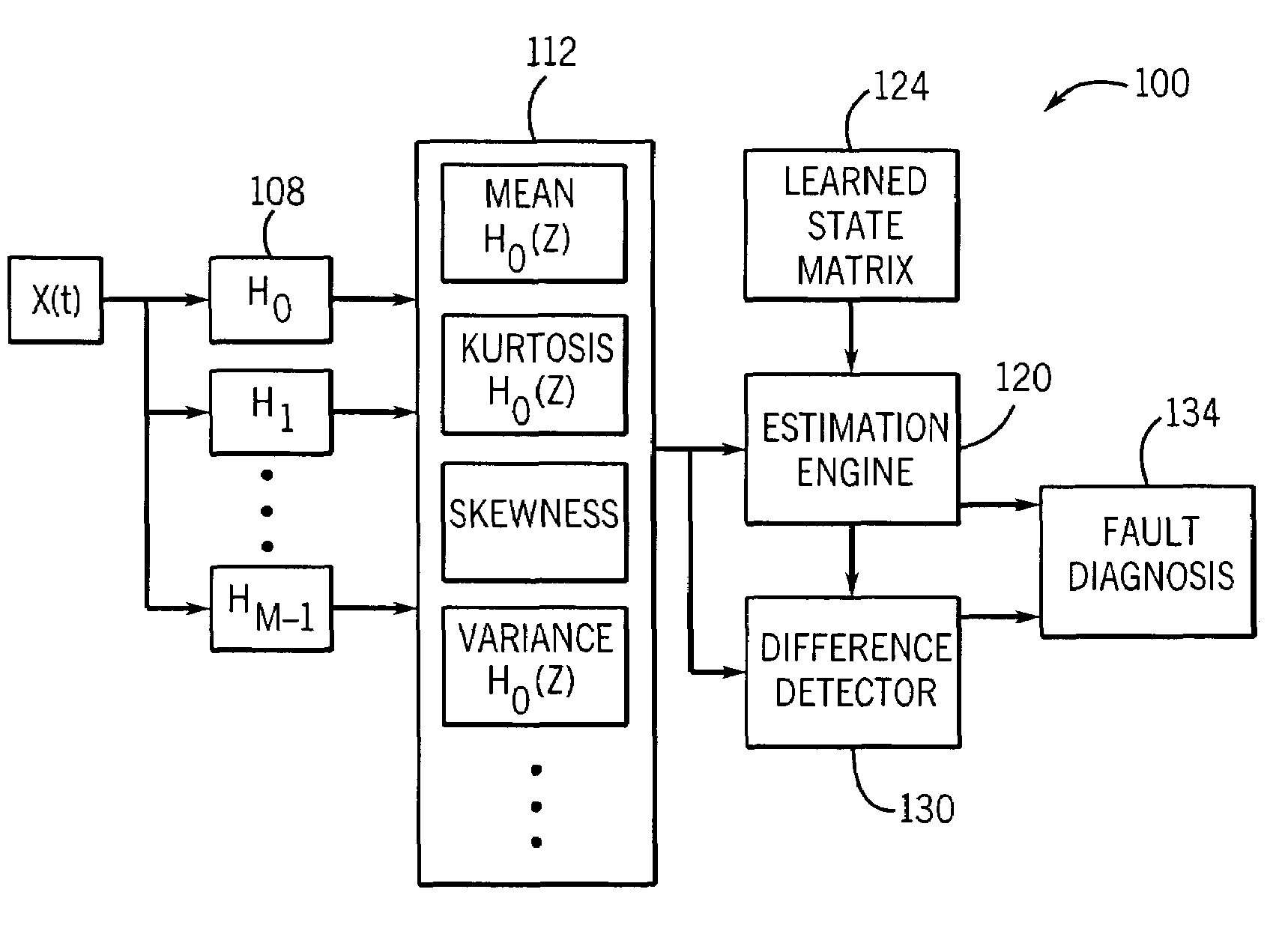
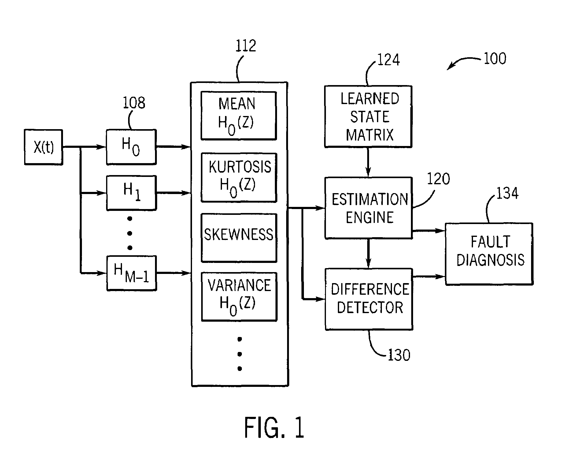
[0019]Turning now to the drawings, FIG. 1 generally shows the preferred embodiment of system 100. A signal x(t) represents some complex measured value from the monitored system being monitored, for example vibration from an accelerometer or sound level from an acoustic pick-up. M-channel filter bank 108 comprises m filters and is disposed to receive the input signal x(t) and decompose it into sub-band components. Feature extraction module 112 receives the sub-band components and generates features such as mean, variance, skewness and kurtosis for at least some of the sub-band components, over a shifting window of time samples. Estimation engine 120 receives the feature value sequences from the feature extraction module 112, and with reference to a learned state matrix 124, generates estimates for the features. These estimates are compared to the feature values determined by the module 112 in a difference detector module 130, which may employ statistical differencing tests over seque...


PUM


Abstract

A system, method and program product for predictive condition monitoring of a monitored system by means of sub-band decomposition of a complex monitored signal. Features of the decomposed signal are extracted for modeling estimation and detection of deviations in the features. Deviations are indicative of impending monitored system fault.

Description

CROSS-REFERENCE TO RELATED PATENT APPLICATIONS[0001]This application claims priority to U.S. provisional patent application No. 60 / 354,626 which was filed on Feb. 6, 2002.BACKGROUND OF THE INVENTION[0002]1. Field of the Invention[0003]The present invention relates to process and machine modeling and system monitoring, especially for predictive condition monitoring. More particularly, the invention relates to condition monitoring of a system using an empirical model having inputs derived from complex signal decomposition using a sub-band technique.[0004]2. Description of the Related Art[0005]A number of advanced techniques have been developed to provide improved monitoring and control of equipment and processes, for example in an industrial setting. Such techniques have the potential of providing earlier detection of equipment failure and process upset, as well as finer control, and offer an alternative to simpler, threshold-based alarm condition monitoring systems, which merely exam...

Claims


Application Information

Patent Timeline
Patent Type & Authority Patents(United States)
IPC IPC(8): G06F17/18G06F17/00G05B23/02G06F11/34
CPCG05B23/024G06F11/3452
Inventor WEGERICH, STEPHAN W.
Owner UNIVERSITY OF CHICAGO
Why Eureka
Try Eureka