Template for positioning vents or boots for an HVAC system

a technology for positioning vents and hvac systems, which is applied in the field of tools for helping install hvac systems, can solve the problems of inability to accurately define a location, inaccurate hvac vents, and time-consuming tasks, and achieve the effect of reducing the cost and increasing the efficiency of an hvac system

Inactive Publication Date: 2006-08-08
LAWSON MARK
View PDF20 Cites 28 Cited by
  • Summary
  • Abstract
  • Description
  • Claims
  • Application Information

AI Technical Summary

Benefits of technology

[0008]The present subject matter recognizes and addresses the above briefly discussed drawbacks, and others of the above-described process for defining locations of vents for an HVAC system. Accordingly, a general aspect of the present subject matter is to provide a tool that can increase the efficiency and thereby decrease the cost of an HVAC system. Additional aspects and advantages of the invention will be set forth in part in the following description, or may be obvious from the description, or may be learned through practice of the invention.

Problems solved by technology

The defining of the positions for an HVAC boot with a straightedge and tape measure can be time consuming and the opportunity for inaccuracies in defining a location may be great.
If such considerations are not taken, the placement of the position for the HVAC vent may be inaccurate causing a reworking of not only the position of the HVAC vent but possibly the subflooring, flooring or sheetrock, depending on the location of the vent.
This “roughing-in” for position of an HVAC boot is a time consuming task.
Further, as stated above, the opportunity for an imperfect placement such as a crooked placement or placements which interfere with the molding around a wall happen all too often when the HVAC installer uses a tape measure and a straightedge to define the position.
The same problem often occurs for installations of boots in ceiling positions in new construction sites.
For example, such occurrences may happen due to the installer not understanding the width of the molding that will be placed along the ceiling and corresponding wall, or due to the indecision of the owner of the premises who may decide at a later date to have different size moldings.
To correct his misplacements of the boots, the installer of the HVAC will have to cut into the molding, creating an unsightly divot in the molding.

Method used


Image

  • Template for positioning vents or boots for an HVAC system
  • Template for positioning vents or boots for an HVAC system
  • Template for positioning vents or boots for an HVAC system

Examples


Embodiment Construction

[0025]Reference will now be made in detail to the presently preferred embodiments of the invention, one or more examples of which are shown in the figures. Each example is provided to explain the invention, and not meant as a limitation of the invention. In fact, features illustrated or described as part of one embodiment can be used with another embodiment to yield still a third embodiment. It is intended that the present invention covers such modifications and variations.

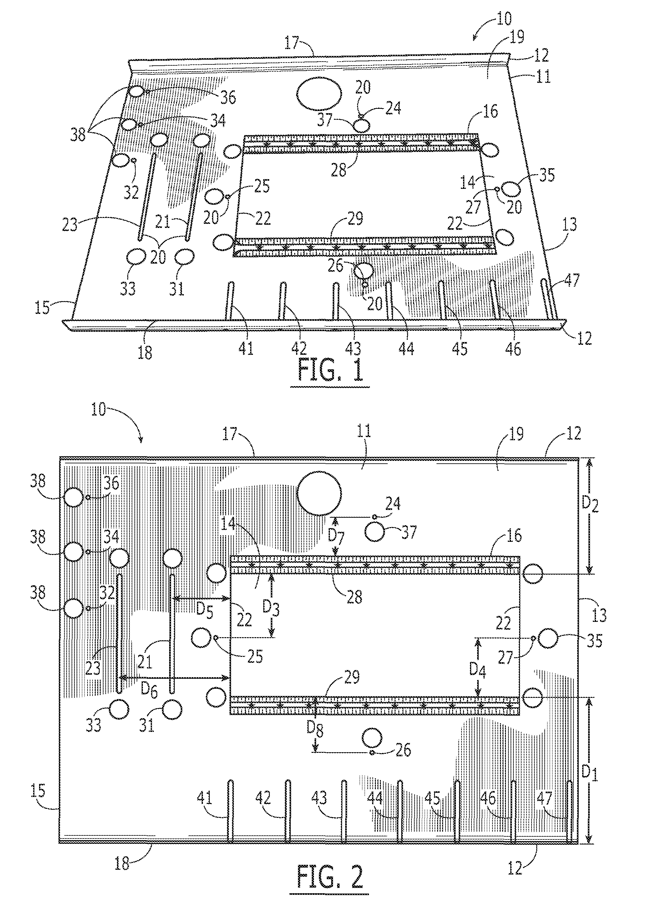
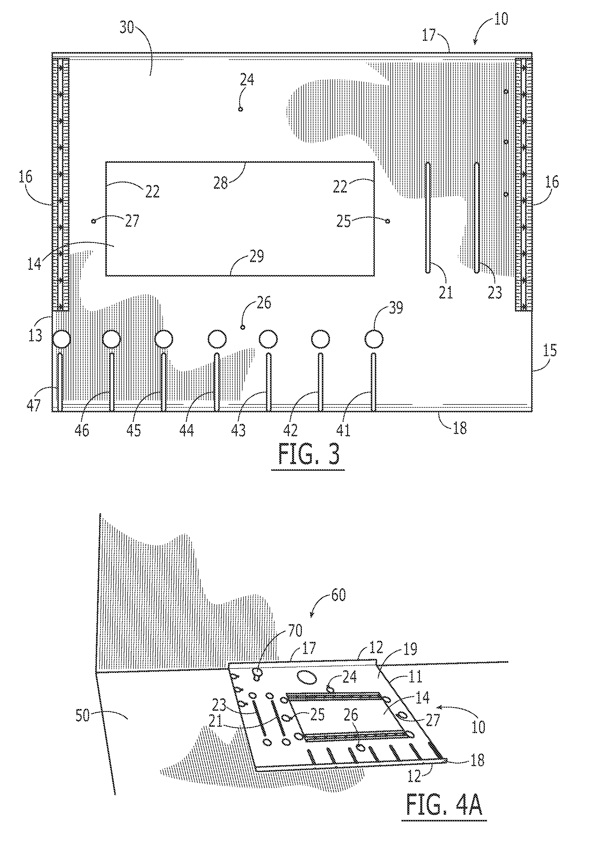
[0026]FIGS. 1, 2 and 3 illustrate a perspective view, top view, and bottom view of a template, generally 10, used for the installation of boots or vents within a building for an HVAC system. The exemplary embodiment of the template 10 may serve up to three functions in designating the location of HVAC boots or vents. Thus, if desired, the template can be used to locate such boots on a floor, ceiling, and / or wall. The template 10 has a body 11 made of a rigid and durable material. The body 11 may be constructed of ...


PUM


Abstract

A template for locating the placement of the vents for an HVAC system is provided. The template includes a body defining a first set of parallel edges. Further, the body defines longitudinal and latitudinal walls of a rectangular aperture. The longitudinal walls run parallel to the first set of parallel edges and the latitudinal walls run perpendicular to the first set of parallel edges. The rectangular aperture is useable to define a location of a vent for an HVAC system on at least one of a floor or wall. At least one adjustment aperture is defined by the body beside at least one of the latitudinal or longitudinal walls to accommodate the defining of a location for a vent having at least one of different width or length than provided by the rectangular aperture.

Description

FIELD OF INVENTION[0001]The present invention relates generally to a tool for helping install an HVAC system. More particularly, the invention relates to a template used for defining a location of a boot and vent register for an HVAC system within a building.BACKGROUND OF THE INVENTION[0002]When installing an HVAC system in a house, building or other facility under construction, an important step is to locate the positions of HVAC boots, vents, and vent registers for supplying and returning air within the internal structure of the building. In new construction, the designation of where the boots will be placed may be done before sheetrock is placed on the walls and ceiling and before the floor is installed on the subfloor. When siting these positions for HVAC boots, a worker will use a tape measure and straightedge to trace out the position for the HVAC boot. At a later time, a hole will be cut in the floor for the HVAC boot around the position that has been traced and the boot will...

Claims


Application Information

Patent Timeline
Patent Type & Authority Patents(United States)
IPC IPC(8): G01B5/14
CPCG01B3/14
Inventor LAWSON, MARK
Owner LAWSON MARK
Why Eureka
Try Eureka