
Heat fixing apparatus for sublimating and fixing sublimating ink to recording medium

a technology of sublimation and fixing apparatus, which is applied in the direction of printing, other printing apparatus, etc., can solve the problems of transfer that may not invite deformation in the recording medium, and achieve the effect of reducing waste of heating energy and reliable transfer

Inactive Publication Date: 2006-08-08
NK WORKS CO LTD
View PDF34 Cites 20 Cited by
  • Summary
  • Abstract
  • Description
  • Claims
  • Application Information

AI Technical Summary

Benefits of technology

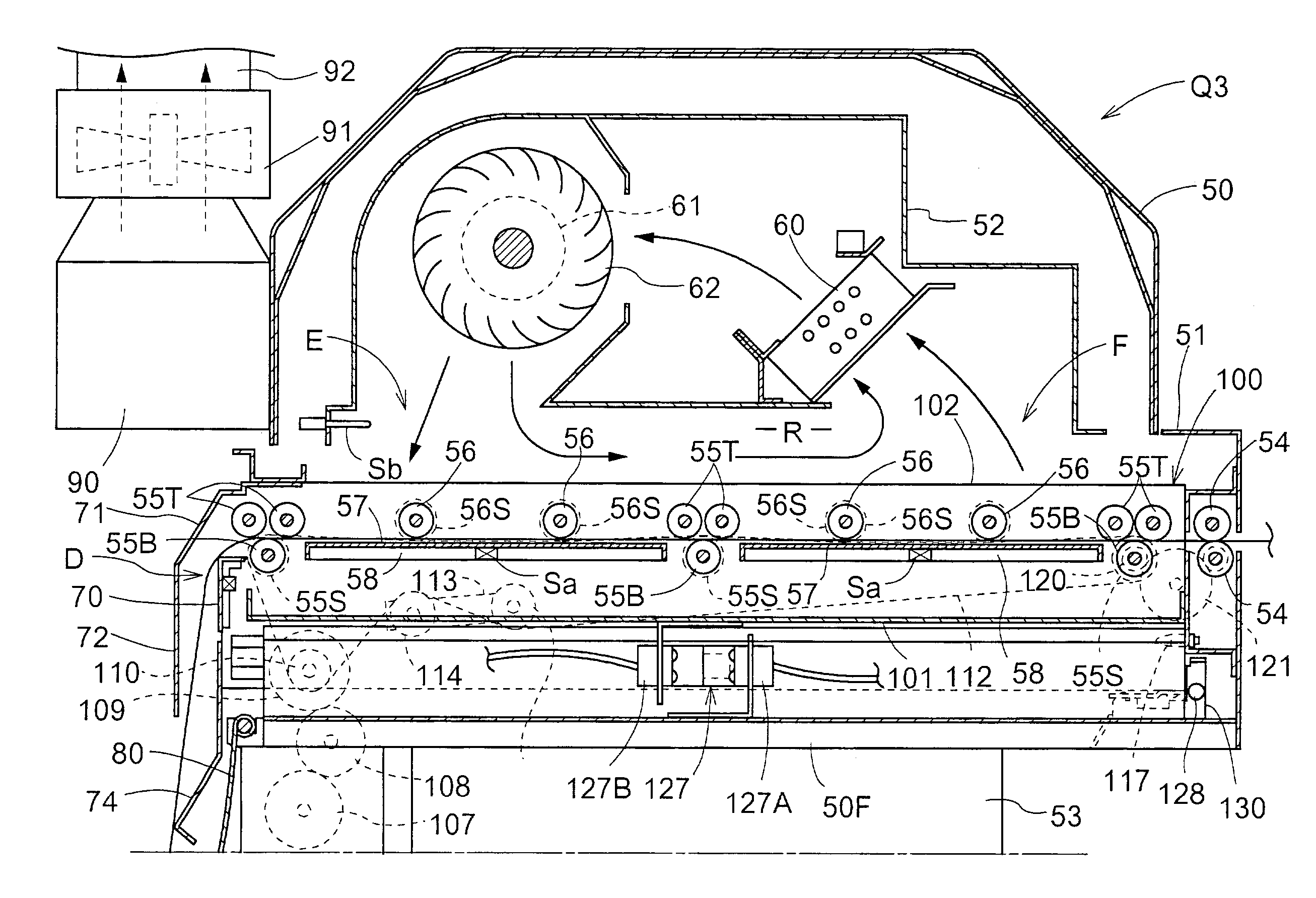
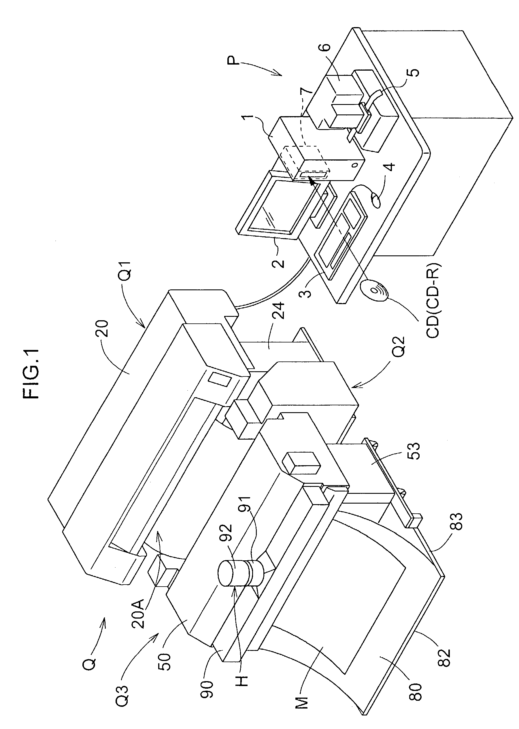
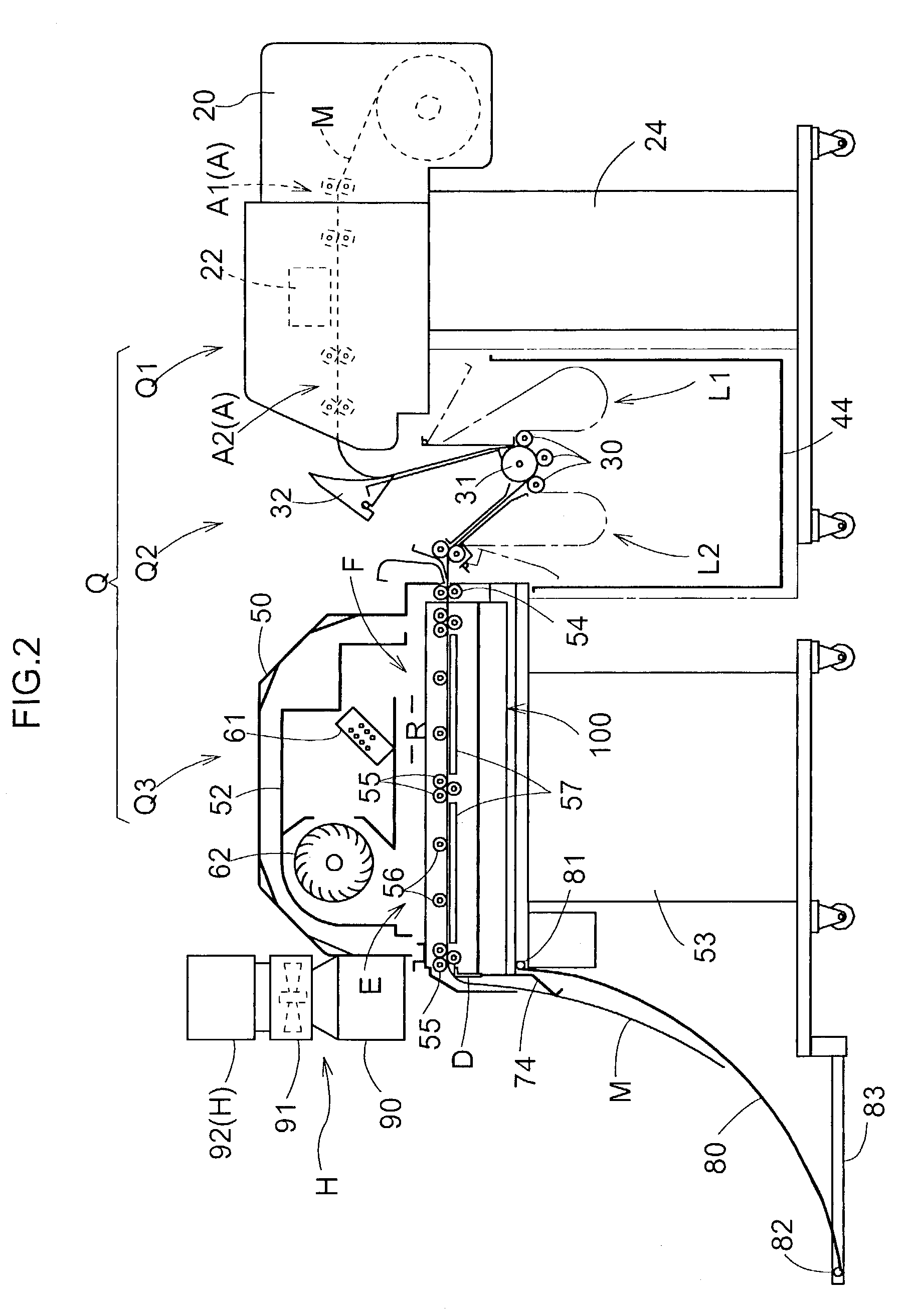
[0013]With the above-described feature, according to the invention's heating fixing apparatus relating to claim 1 while the recording medium is being transported within the heating space by the heating transporting mechanism, the blower mechanism supplies the hot air heated by the heater body to this recording medium, thus realizing the heating of the medium. Further, since this heated air flows in contact with the surface of the recording medium, local heating may be avoided for enabling uniform heating. That is to say, as the air having fluidity is caused to come into contact with a large area of the recording medium, the uniform heating is made possible. As a result, transfer may take place in a favorable manner through the uniform heating provided by the combination of the heater body and the blower mechanism. Moreover, this, transfer may take place without inviting deformation in the recording medium even if this medium employs thermoplastic resin as the substrate thereof.
[0027]With this, the heating transfer process may be effected on the recording medium which is being transported at a set speed, with appropriate adjustment of the width of the heating area of the heating space according to the width of the recording medium. That is to say, by adapting the width of the heating space to the width of the recording medium, heating of space where no heating is needed may be avoided and the recording medium is transported at the set fixed speed, thereby to realize reliable transfer. Consequently, waste of energy required for heating may be eliminated.

Problems solved by technology

Moreover, this, transfer may take place without inviting deformation in the recording medium even if this medium employs thermoplastic resin as the substrate thereof.

Method used


Image

  • Heat fixing apparatus for sublimating and fixing sublimating ink to recording medium
  • Heat fixing apparatus for sublimating and fixing sublimating ink to recording medium
  • Heat fixing apparatus for sublimating and fixing sublimating ink to recording medium

Examples


second embodiment

(Second Embodiment)

[0087]As shown in FIG. 15, outside the heating space R, thee is provided an air heating chamber 150 including an electric heater 60 (an example of the heater body), a fan 62, and a fan motor 61. A pair of feed ducts 151 are provided for feeding hot air heated at this air heating chamber 150 to a space in the heating space R facing the transport passage from opposed sides thereof. A rectifier plate 152 is provided for uniformly distributing the hot air from the feed ducts 151 into the heating space R. Further, a pair of intake ducts 153 are provided for returning the air from the space of the heating space R opposing the transport passage from the opposed sides thereof back to the heating space R. These components together constitute a heating mechanism of this embodiment. With this construction adapted for feeding hot air to the heating space R by means of ducts, by creating the air current at a portion in the heating space R whose temperature is difficult to be r...

third embodiment

(Third Embodiment)

[0088]As shown in FIG. 16 and FIG. 17, a preliminary heating unit HU is provided in the transporting passage for feeding the recording medium M to the heating space R, and at a position where the medium M is discharged from the heating space, there is provided a slow-cooling unit CU.

[0089]That is, this further embodiment does not differ from the foregoing embodiment in the construction of heating the recording medium M at the heating space R formed inside the heating case 51. The preliminary heating unit HU forms a preliminary heating space PR, where a press type introduction roller 54 for feeding the recording medium M to this preliminary heating unit HU, an upper-face contact roller 56 for coming into contact with the upper face of the medium M fed into this preliminary heating space PR for providing a transporting force thereto, and a guide member 57 for contacting the lower face of the recoding medium M for transmitting heat thereto, are provided. On the lower ...

fourth embodiment

(Fourth Embodiment)

[0095]As shown in FIGS. 18 through 20, in this embodiment, the width of the heating area of the heating space R is rendered adjustable according to the width of the recording medium M. In this embodiment, the heat fixing unit Q3 (an example of heat fixing apparatus) is connected with the printing unit Q1.

[0096]More particularly, in the printing unit Q1, within a main body 171 having a cover 170 which can be pivotally opened / closed about a hinge 170a, a support rod 172 rotatably supports the recording medium M in the rolled state. The body 171 accommodates therein a pinching type transporting mechanism A for feeding the recording medium M and an inkjet type print head 22 for printing image information on the recording medium M transporting mechanism A with sublimating ink. This print head 22 is supported to be movable back and forth along a guide rod 24 oriented along the main scanning direction. The head 22 includes an ink cartridge 25 detachably attached to the h...


PUM


Abstract

A heat fixing apparatus has a heating unit for heating a recording medium having a substrate, a fixing layer and a surface layer so as to sublimate sublimating ink applied in advance to the surface layer for transferring the sublimated ink to the fixing layer. The heating unit includes a heating transporting mechanism for transporting the recording medium within a heating space, a heater body for heating air, and a blower mechanism for supplying hot air heated by the heater body to the recording medium being transported by the heating transporting mechanism. The apparatus further includes a flat guide member for coming into contact with the surface of the recording medium being transported by the heating transporting mechanism and a heater for heating the guide member.

Description

BACKGROUND OF THE INVENTION[0001]1. Field of the Invention[0002]The present invention relates to a heat fixing apparatus including a heating unit for heating a recording medium having a substrate, a fixing layer and a surface layer so as to sublimate sublimating ink applied in advance to the surface layer for transferring the sublimated ink to the fixing layer.[0003]2. Description of the Related Art[0004]An exemplary conventional technique relating to the above field of art is disclosed in Japanese patent application “Kokai” No: Hei. 10-297197. According to this, a metal substrate includes a coloring ground layer (corresponding to a “fixing layer” in the present invention) acting also as a rust-preventive layer, a transparent resin layer as an optical transparent resin layer formed over the coloring ground layer, the resin layer being made of acrylic resin, polyester resin, urethane resin etc., and an inkjet receiving layer (corresponding to a “surface layer” in the present inventio...

Claims


Application Information

Patent Timeline
Patent Type & Authority Patents(United States)
IPC IPC(8): B41J2/01B41J11/00B41J13/10B41J15/00
CPCB41J11/0005B41J11/002B41J15/005B41J13/106B41J11/0045B41J11/00222B41J11/0024B41J11/00224
Inventor NISHIKAWA, HIDETOSHISHIMA, KAZUNOBUISHIKAWA, MASAZUMINAGAOSA, KAZUONAKAMOTO, MASAKIINOSHITA, MASANORIFUNASE, MASASUKEMATSUOKA, TOSHIHIRO
Owner NK WORKS CO LTD
Learn More