
Contact ring with embedded flexible contacts

a flexible contact and contact ring technology, applied in the field of electrochemical plating, can solve the problems of substrate breakage, inability to support device formation, and difficulty in filling void-free interconnect feature by conventional metallization techniques, and achieve the effect of maintaining electrical isolation of the body portion

Inactive Publication Date: 2006-08-08
APPLIED MATERIALS INC
View PDF101 Cites 35 Cited by
  • Summary
  • Abstract
  • Description
  • Claims
  • Application Information

AI Technical Summary

Benefits of technology

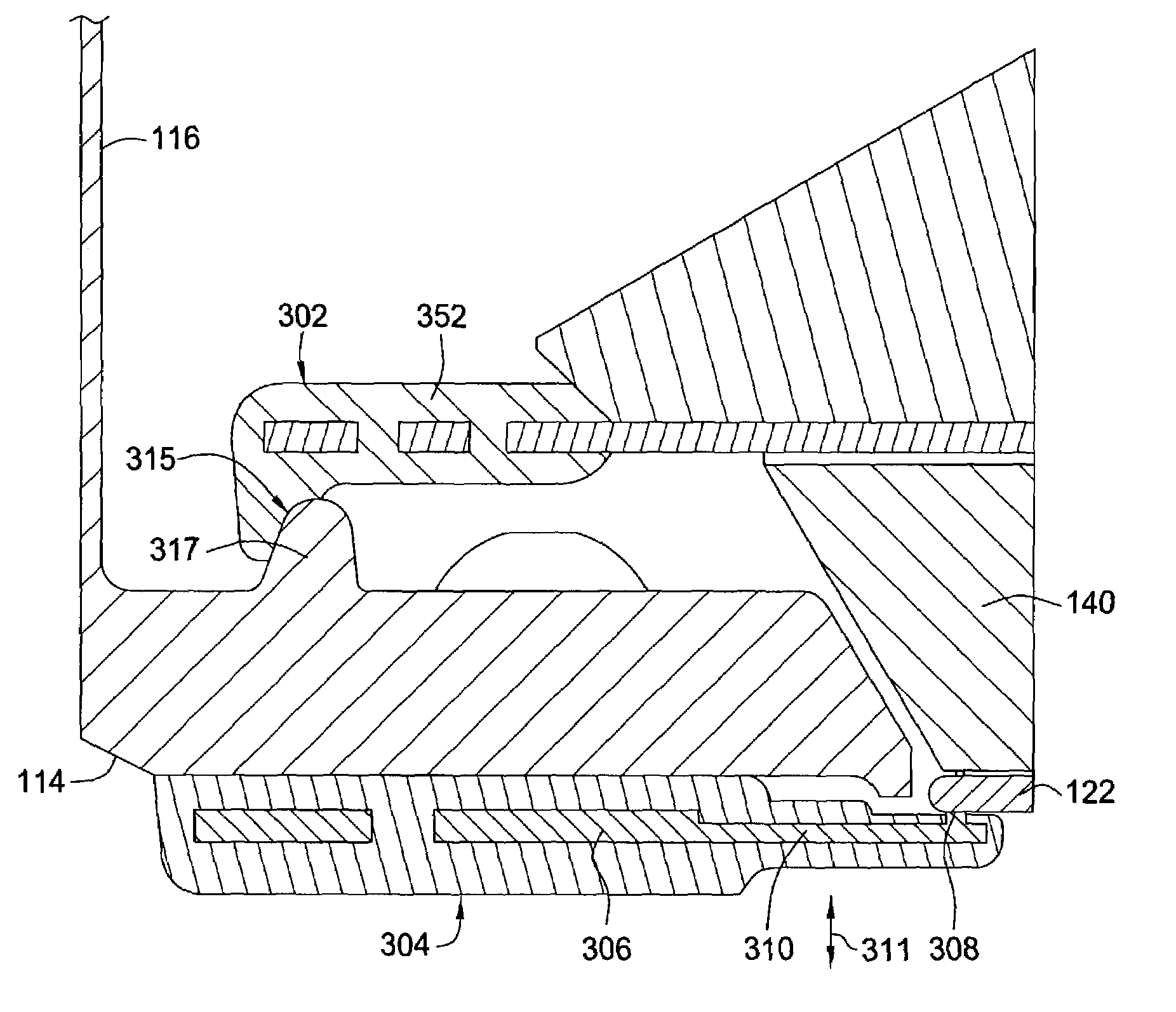
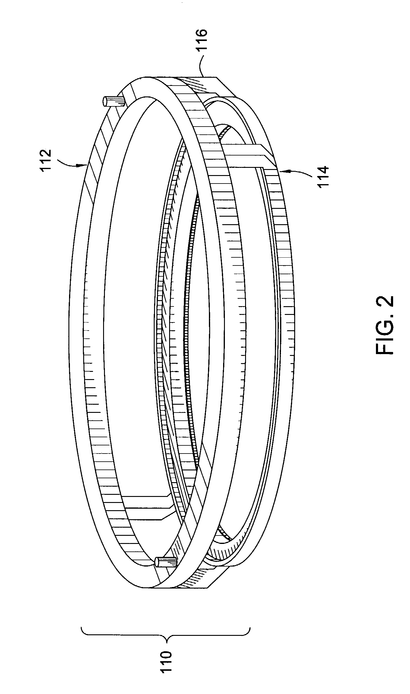
[0011]Embodiments of the invention further provide a contact ring for an electrochemical plating system. The contact ring generally includes an upper ring member, a lower ring member secured to the upper ring member via a plurality of support members, the lower ring member having an inwardly extending flange, a plurality of vertically flexible conductive contact pins extending radially inward from the lower ring member, an electrically insulating layer covering the plurality of the vertically flexible conductive contact pins, and a plurality of conductive tip members affixed to a terminating end of each of the plurality of vertically flexible conductive contact pins.
[0012]Embodiments of the invention further provide a substrate contact assembly for an electrochemical plating system. The substrate contact assembly generally includes an electrically conductive contact ring, a first electrically insulating layer covering outer surfaces of the contact ring, a plurality of electrically conductive flexible contact fingers extending radially inward from the contact ring, and a second electrically insulating layer covering a body portion of the contact fingers, the second electrically insulating layer being configured to flex with the contact fingers while maintaining electrical isolation of the body portion.

Problems solved by technology

However, as the interconnect sizes decrease and aspect ratios increase, void-free interconnect feature fill via conventional metallization techniques becomes increasingly difficult.
Since this surface area is used to make electrical and seal contacts, the area cannot be used to support device formation.
However, without sealing members or electrical contacts on the plating surface to support the substrate, some other means may be needed to support the substrate.
However, the vacuum applied to the substrate may create a stress on the substrate, and may lead to substrate breakage.
If the sealing members happen to leak, the vacuum may be unable to maintain the substrate against the electrical contacts with sufficient force and the plating solution may enter the vacuum, causing damage to the vacuum.
Although the concept of dry contact pins is noteworthy, there are several disadvantages of these configurations.
Namely, dry contact configurations present challenges in maintaining a fluid tight seal between the substrate, and as such, fluid often penetrates the seals and is exposed to the contact pins, which alters the pin resistance and the plating uniformity.

Method used


Image

  • Contact ring with embedded flexible contacts
  • Contact ring with embedded flexible contacts
  • Contact ring with embedded flexible contacts

Examples


Embodiment Construction

[0018]Embodiments of the invention generally provide a contact ring configured to secure and electrically contacting a substrate in an electrochemical plating system. The contact ring generally includes a plurality of electrical contact pins radially positioned and configured to electrically contact a substrate being plated proximate the perimeter of the substrate. Further, although the contact pins are embedded within an insulative body, the contact pins are configured to be partially flexible and implemented in a wet contact configuration.

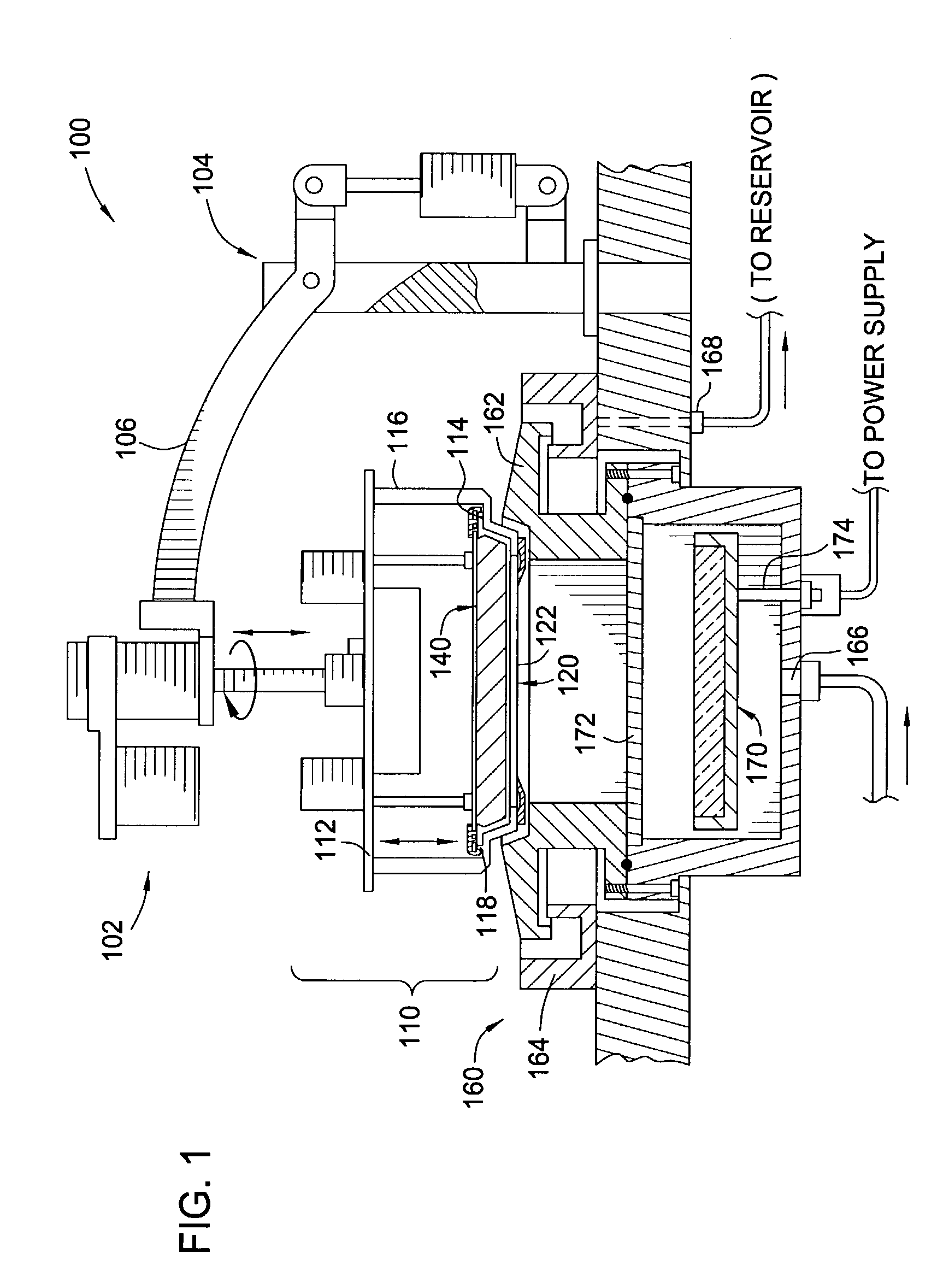
[0019]FIG. 1 illustrates a sectional view of an exemplary electrochemical plating (ECP) system 100 of the invention. The ECP system 100 generally includes a head assembly actuator 102, a substrate holder assembly 110, and a plating basin assembly 160. The head actuator assembly 102 is generally attached to a supporting base 104 by a pivotally mounted support arm 106. The head actuator assembly 102 is adapted to support the substrate holder assemb...


PUM

PropertyMeasurementUnit
outer diameteraaaaaaaaaa
flexibleaaaaaaaaaa
conductiveaaaaaaaaaa

Abstract

A contact assembly for supporting a substrate in an electrochemical plating system, wherein that contact assembly includes a contact ring and a thrust plate assembly. The contact ring includes an annular ring member having an upper surface and a lower surface, an annular bump member positioned on the upper surface, and a plurality of flexible and conductive substrate contact fingers extending radially inward from the lower surface. The thrust plate includes an annular plate member sized to be received within the annular ring member, and a seal member extending radially outward from the plate member, the seal member being configured to engage the annular bump member for form a fluid seal therewith.

Description

BACKGROUND OF THE INVENTION[0001]1. Field of the Invention[0002]Embodiments of the invention generally relate to electrochemical plating and, more particularly, to a contact ring for an electrochemical plating system.[0003]2. Description of the Related Art[0004]Metallization of sub-quarter micron sized features is a foundational technology for present and future generations of integrated circuit manufacturing processes. More particularly, in devices such as ultra large scale integration-type devices, i.e., devices having integrated circuits with more than a million logic gates, the multilevel interconnects that lie at the heart of these devices are generally formed by filling high aspect ratio (greater than about 4:1, for example) interconnect features with a conductive material, such as copper or aluminum, for example. Conventionally, deposition techniques such as chemical vapor deposition (CVD) and physical vapor deposition (PVD) have been used to fill these interconnect features....

Claims


Application Information

Patent Timeline
Patent Type & Authority Patents(United States)
IPC IPC(8): C25D17/06C25D17/08C25D3/38C25D7/12
CPCC25D17/06C25D17/001C25D7/123C25D17/12
Inventor HERCHEN, HARALD
Owner APPLIED MATERIALS INC
Learn More