Multi-shelved convection microwave oven

a microwave oven and convection technology, applied in the field of multi-shelved ovens, can solve the problems of inability to cook different foods simultaneously with different heating conditions, and the inability to provide the flexibility of the cook cycle, so as to achieve efficient and even

Inactive Publication Date: 2006-08-08
ENERSYST DEV CENT
View PDF13 Cites 110 Cited by
  • Summary
  • Abstract
  • Description
  • Claims
  • Application Information

AI Technical Summary

Benefits of technology

[0010]In a preferred embodiment of the invention, the cooking chamber comprises a first cooking cavity and a second cooking cavity and includes a first shelf and a second shelf. The first shelf has an inlet opening and cavity in fluid communication with a blower and the second shelf has an inlet opening and cavity in fluid communication with a blower. Further, both the first and second shelves have at least one opening in fluid communication with the first cooking cavity and second shelf having at least one opening in fluid communication with said second cooking cavity, respectively. In a preferred aspect of this embodiment, microwave heating is provided in the first and second cavities through wave guides, preferably a pair of wave guides associated with each cavity. The preferred wave guide arrangement again provides a wave guide having a predetermined minima and maxima and openings in the wave guide positioned to substantially correspond the minima or maxima, thereby providing efficient and even distribution of microwave energy into the cooking cavities along the length of the wave guide.

Problems solved by technology

While such ovens meet the needs of certain commercial food service applications by providing rapid thermalization and cooking, the inability to cook different foods simultaneously with different heating conditions and cook cycles does not provide needed flexibility.

Method used


Image

  • Multi-shelved convection microwave oven
  • Multi-shelved convection microwave oven
  • Multi-shelved convection microwave oven

Examples


Embodiment Construction

[0036]The description of the invention provided below is made with reference to the drawings attached hereto. The drawings have been consecutively numbered as FIGS. 1–23.

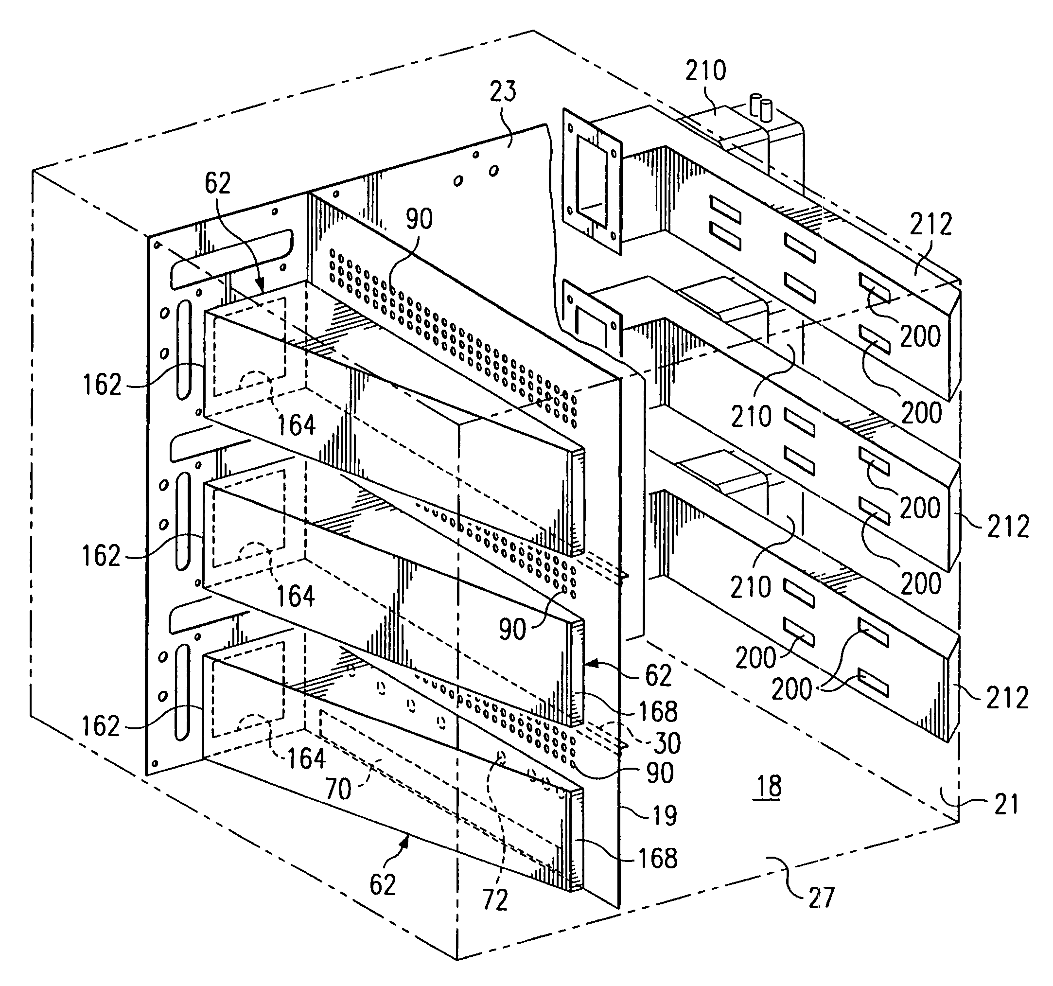
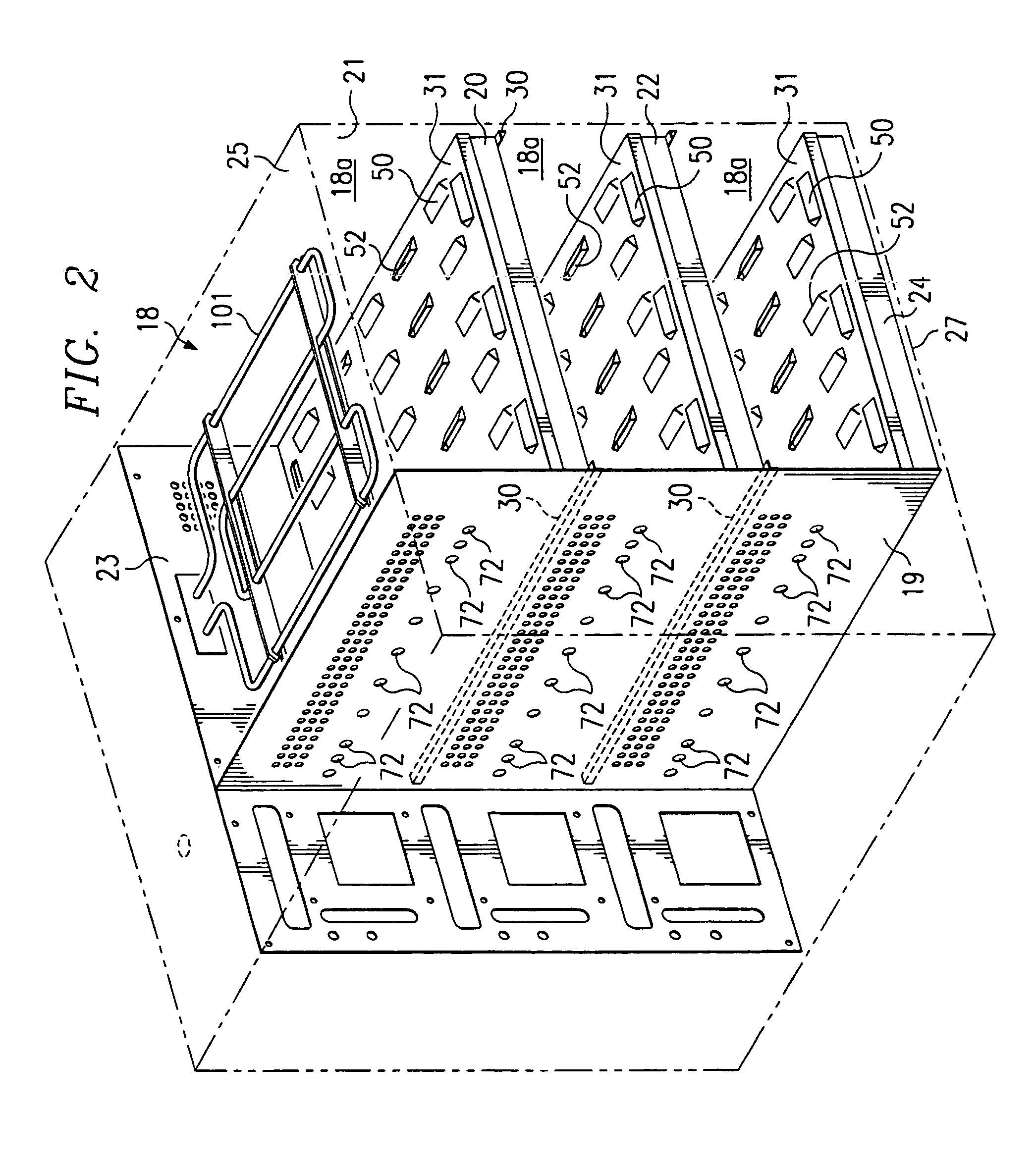
[0037]In FIG. 1, there is shown one embodiment of the oven 10 of the present invention. Oven 10 includes an exterior cabinet 12 defined by exterior side walls, exterior top and bottom walls and an exterior rear wall. Preferably said walls are constructed of a stainless steel material. Hingedly secured to the front of the oven is door 14 which permits food products to be placed in and out of the interior of the oven. A handle 16 with latching means is secured to door 14 to allow the door to be secured in a closed position during cooking. The door 14 is designed by known conventional means for preventing microwave leakage from the chamber 18 while the door is closed. Referring to FIGS. 2–4, 16–17 and 19, chamber 18 is defined by interior side walls 19 and 21, back wall 23, top wall 25 and bottom wall 27 (collectively ...


PUM


Abstract

An oven, is provided that includes multiple heat transfer means, including convection and microwave heat transfer means. The oven includes a cooking chamber, a blower and at least a shelf disposed within the cooking chamber. The shelf is designed to act as a food support as well as a conduit through which heated air passes into the cooking chamber. The microwave heating means comprises a microwave source and wave guide through which microwaves travel. The wave guide includes a plurality of openings through which microwaves can pass into said cooking chamber. In the preferred embodiment, the openings in the wave guide are positioned to correspond with the predetermined minima or maxima for the microwave wavelength propagating within the wave guide. An electric heating element may also be disposed within the cooking chamber to provide an alternative heating source.

Description

CROSS-REFERENCE TO RELATED APPLICATION[0001]This application is related to U.S. Provisional Patent Application Ser. No. 60 / 130,067 filed Apr. 19, 1999, the entire contents of which are incorporated herein by reference.FIELD OF THE INVENTION[0002]The present invention relates to a multi-shelved oven having multiple heating means, including convection, microwave and radiant food heating means.BACKGROUND OF THE INVENTION[0003]The oven disclosed herein relates primarily to ovens suitable for use in the commercial food service industry, such as fast food restaurants, and other food service application where there is great variety in the food products prepared, the need for speedy thermalization of food and space constraints. While various oven designs are known and available for commercial food service applications, there still exists a need for an efficient and effective oven that allows for simultaneous cooking of different food products requiring different heat treatments. Single cavi...

Claims


Application Information

Patent Timeline
Patent Type & Authority Patents(United States)
IPC IPC(8): H05B6/70H05B6/80
CPCF24C15/166H05B6/6408H05B6/6485H05B6/745H05B6/80H05B6/708H05B2206/044
Inventor DOBIE, MICHAEL J.NORRIS, JOHN ROBERTCOOPER, NEAL S.BACIGALUPE, CARLOSFOREMAN, ROBERT W.
Owner ENERSYST DEV CENT
Why Eureka
Try Eureka