
Ruggedized illuminating, marking, or signaling device and system

Active Publication Date: 2006-08-08
POWERFLARE CORP
View PDF27 Cites 103 Cited by
  • Summary
  • Abstract
  • Description
  • Claims
  • Application Information

AI Technical Summary

Benefits of technology

[0012]An illumination device, including: a shell with a plurality of sides, where the device can be positioned upon a surface or attached or suspended from any of the plurality of sides; and at least one light-emitting device within the shell, where when the device is positioned upon a surface or attached or suspended from any of the plurality of sides of the shell, light from the at least one light-emitting device emits through each of the plurality of sides of the shell. The device is thus easy to deploy and use. Its design is compatible with outsourced manufacturing, allowing for cost savings. The device can be reused many times, and its external coloring or color pattern can be designed for the application. The devices have a means to communicate internally and externally, forming a network. The device can also emit light for many hours longer and has ruggedness that far exceeds conventional devices. The device can also be used where conventional devices and other lighting devices cannot, including underwater and in the presence of hazardous materials.

Problems solved by technology

Mechanically Frail: The devices generally cannot withstand the rigors of heavy use, such as being run over by large trucks, and the devices cannot withstand sustained exposure to harsh environments or hazardous materials.
The failure of such devices eliminates the cost savings that might otherwise have been realized.
Poor Power Management: Most products use non-rechargeable power sources, requiring the user to frequently replace the power source or the product itself, introducing uncertainty as to the readiness of the unit.
Many products that use rechargeable power sources manage the stored power inefficiently.
Inadequate Optical Visibility: The devices do not have enough visibility to be used in daylight and even nighttime performance is subpar.
Ergonomics: Some of the devices are too bulky, require alkaline batteries that are a maintenance hassle, and require manual activation.
For example, the use of incendiary flares poses numerous problems: they are a serious fire hazard and cannot be used in areas where dry brush or other hazardous or flammable materials are present; they can become chemically unstable over time; they are difficult and dangerous to deploy as a police officer must stand in the road while igniting the flares, sometimes exposed to high-speed traffic and poor visibility; they are susceptible to moisture as well as temperature changes; they are bulky; they have a limited burn time; they are conventionally manufactured with toxic materials; and they are expensive.

Method used


Image

  • Ruggedized illuminating, marking, or signaling device and system
  • Ruggedized illuminating, marking, or signaling device and system
  • Ruggedized illuminating, marking, or signaling device and system

Examples


Embodiment Construction

[0024]The present invention provides an improved illumination device and system. The following description is presented to enable one of ordinary skill in the art to make and use the invention and is provided in the context of a patent application and its requirements. Various modifications to the preferred embodiment will be readily apparent to those skilled in the art and the generic principles herein may be applied to other embodiments. Thus, the present invention is not intended to be limited to the embodiment shown but is to be accorded the widest scope consistent with the principles and features described herein.

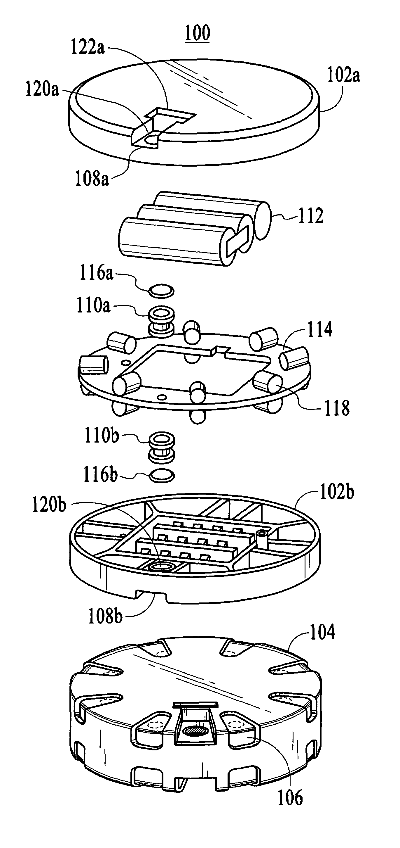
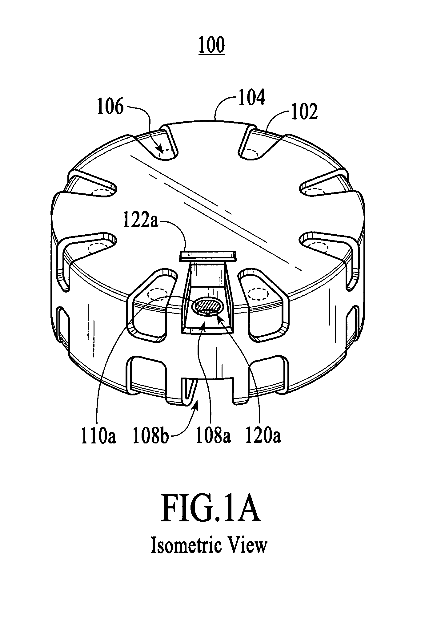
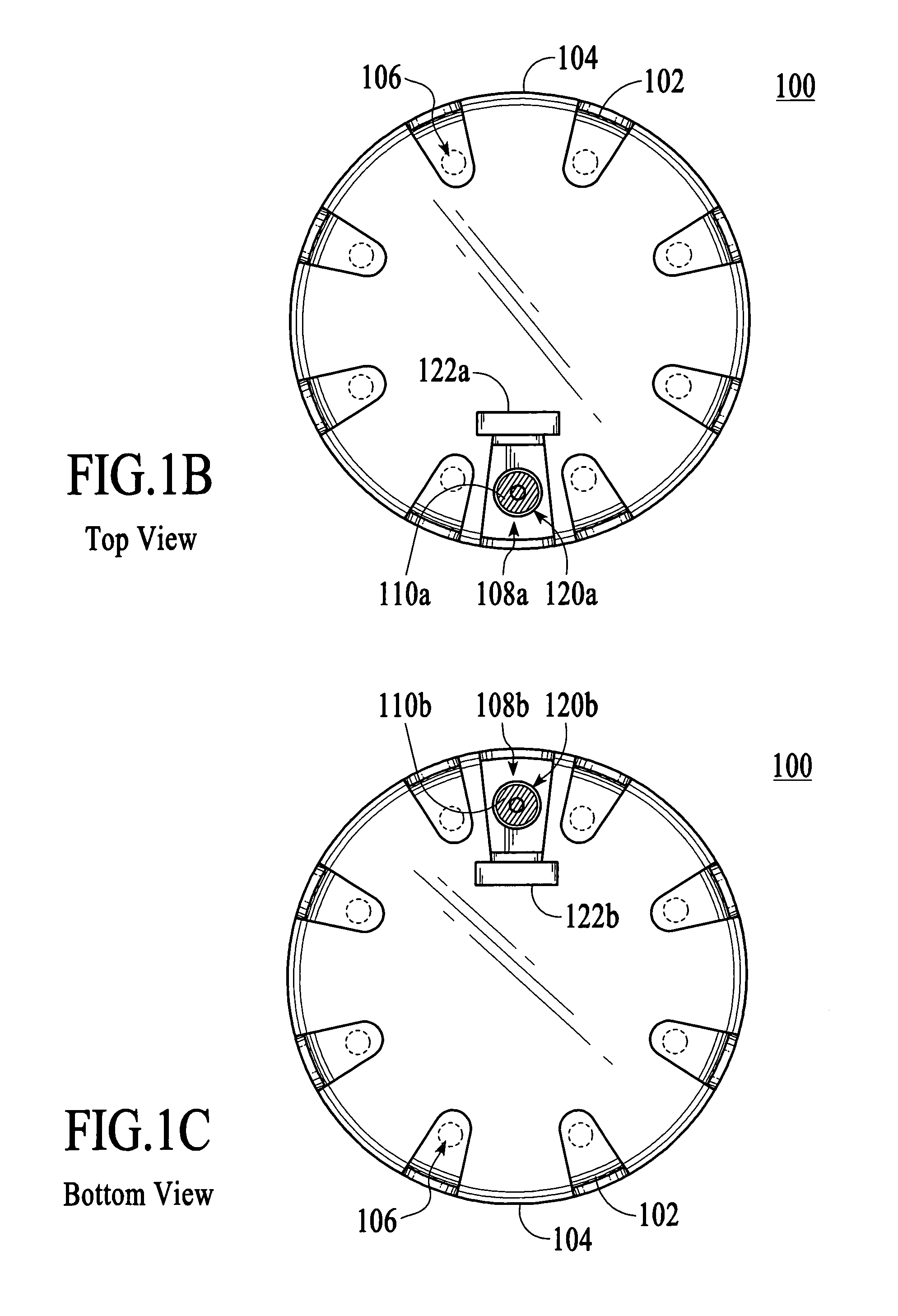
[0025]To more particularly describe the features of the present invention, please refer to FIGS. 1A through 11 in conjunction with the discussion below.

[0026]FIGS. 1A–1G illustrate an isometric, top, bottom, front, left, right and back views, respectively, of a first preferred embodiment of an illumination device in accordance with the present invention. The device 100...


PUM


Abstract

An illumination device, including: a shell with a plurality of sides, where the device can be positioned upon a surface or attached or suspended at any of the plurality of sides; and at least one light-emitting device within the shell, where when the device is positioned upon a surface or attached or suspended at any of the plurality of sides of the shell, light from the at least one light-emitting device emits through each of the plurality of sides of the shell. The device is thus easy to deploy and use. Its design is compatible with outsourced manufacturing, allowing for cost savings. The device can be reused many times. The device can also emit light for many hours longer and has ruggedness that far exceeds conventional devices. The device can also be used where conventional devices and other lighting devices cannot, including underwater.

Description

CROSS-REFERENCE TO RELATED APPLICATIONS[0001]This application claims priority from co-pending U.S. Provisional Patent Application Ser. No. 60 / 426,248, entitled “Ruggedized Electronic Traffic Safety Device and Automated Vehicle Deployment System,” filed on Nov. 13, 2002.[0002]This application is related to co-pending regular U.S. patent application Ser. No. 10 / 712,714 entitled “Deployment System for Ruggedized Illuminating, marking, or Signaling Device, filed on Nov. 12, 2003.FIELD OF THE INVENTION[0003]The present invention relates to electronic devices, and more particularly to illuminating, marking, or signaling electronic devices.BACKGROUND OF THE INVENTION[0004]Various illuminating, marking, and / or signaling electronic devices exist in the safety industry. For example, law enforcement officers use strobes to increase the visibility of their vehicles. Incendiary flares are chemical devices that often mark roads at the scene of an accident or road closures. Various illuminating de...

Claims


Application Information

Patent Timeline
IPC IPC(8): G08B23/00
CPCB60Q7/00F21L4/08F21V15/01F21V19/001F21S9/02F21Y2101/02F21V23/0442F21V25/12F21V31/00F21W2111/02F21Y2107/90F21Y2115/10
Inventor DUEKER, KENNETH S.HAGELIN, PAUL M.EDWARDS, TROY J.TAVERNETTI, RUSSELL E.
Owner POWERFLARE CORP
Learn More