Method and apparatus for controlling common mode electrode voltage in LCOS/LCD

a common mode electrode and voltage control technology, applied in the field of lcos/lcd video projection systems, can solve the problems of affecting the device lifetime, affecting the ability of lcos/lcd to adjust the common mode electrode voltage, and drifting with time and temperature, so as to prevent the possibility of damage to the imager on initial power-up and minimize image sticking

Inactive Publication Date: 2006-08-08
INTERDIGITAL CE PATENT HLDG
View PDF7 Cites 6 Cited by
  • Summary
  • Abstract
  • Description
  • Claims
  • Application Information

AI Technical Summary

Benefits of technology

[0009]In accordance with the inventive arrangements, at least one sensor is used in the system in order to make the common mode electrode adjustment in a continuous manner using feedback. This can be achieved in several ways in accordance with the inventive arrangements. The first system-level implementation places one or more sensors in the overscan area of the picture. A video signal with the appropriate color and drive level is preferably applied to the imager in order to measure the flicker. A chassis microprocessor can then be programmed to read positive and negative field detector voltages and determine the difference between them. This difference can be advantageously used as feedback to adjust the common mode electrode voltage. Such feedback prevents the possibility of damage to the imager on initial power-up due to an incorrect common mode voltage. Such feedback also ensures that the common mode electrode will be re-adjusted dynamically to minimize image sticking.

Problems solved by technology

Setting VITO in this manner avoids both flicker and image retention, both of which can adversely affect the device lifetime.
As this setting is now accomplished by an open-loop control, there is opportunity for error in VITO, and drift with time and temperature.
However, the higher frame rate makes adjustment of the common mode electrode voltage more difficult, as the flicker is not visible to the human eye.
Unfortunately, this open-loop adjustment can be insufficient due to thermal effects in the system.

Method used


Image

  • Method and apparatus for controlling common mode electrode voltage in LCOS/LCD
  • Method and apparatus for controlling common mode electrode voltage in LCOS/LCD
  • Method and apparatus for controlling common mode electrode voltage in LCOS/LCD

Examples


Embodiment Construction

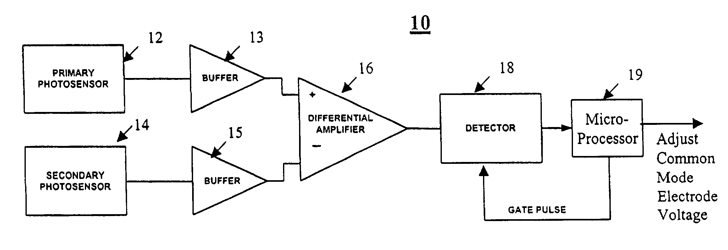
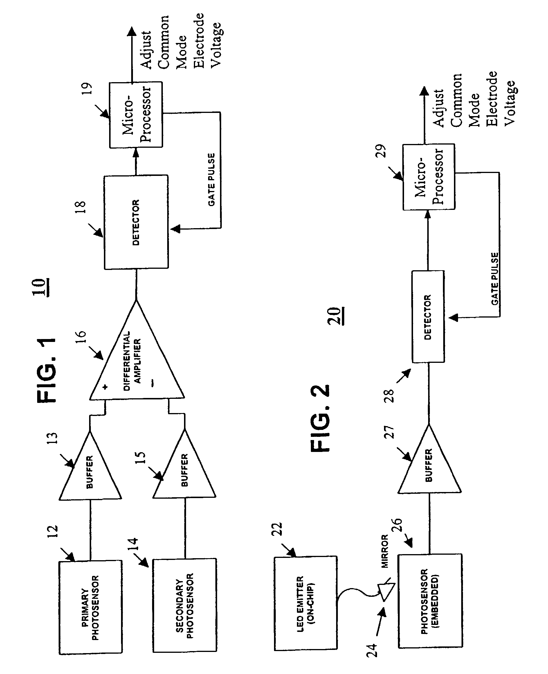
[0014]A block diagram of a presently preferred embodiment is shown in FIG. 1. This embodiment 10 uses two sensors, denoted as a primary sensor 12 and a secondary sensor 14, in order to avoid the problems of rejection of ambient light. The differential sensing between the two sensors will subtract out the common-mode signal due to ambient room light. The two sensors can be placed a short distance apart (e.g., 1–2 inches) in the overscan area of the picture. Alternately, the sensors can be placed at other locations in the light path, including under the fold mirrors that typically are found in a television cabinet in the case of systems without overscan. Pinholes, either intentional or naturally occurring, would allow sufficient light to reach the detectors. The differential sensing between the sensors 12 and 14 is preferably achieved by taking the respective outputs of the sensors and buffering them though respective buffers 13 and 15 and using the buffered outputs as inputs to a dif...


PUM

PropertyMeasurementUnit
distanceaaaaaaaaaa
voltageaaaaaaaaaa
areaaaaaaaaaaa

Abstract

A device for controlling common mode electrode voltage in a liquid crystal display includes at least a first sensor for measuring flicker resulting from applying a video signal with a predetermined color and drive level to an imager. A detector for determining a difference between a positive field detector voltage and a negative field detector voltage is used to provide a feed-back loop for feeding back the difference to a controller to adjust the common mode electrode voltage.

Description

[0001]This application is a 371 of International Application PCT / US01 / 44803, filed Nov. 29, 2001, which claims the benefit of U.S. Provisional Application 60 / 250,273, filed Nov. 30, 2000.BACKGROUND OF THE INVENTION[0002]1. Technical Field[0003]The invention arrangements relate to the field of LCOS (liquid crystal on silicon) and / or LCD (liquid crystal display) video projection systems. More particularly, the inventive arrangements taught herein are related to automatically adjusting the common-mode electrode voltage in LCOS / LCD projection systems.[0004]2. Description of Related Art[0005]In LCOS systems, it is necessary to set the common mode electrode voltage to be precisely between the positive and negative drive voltages to the pixel. It is typical to drive the imager of an LCOS display with a frame-doubled signal to avoid 30 Hz flicker, by sending first a normal frame in which the voltage at the electrodes associated with each cell is positive with respect to the voltage at the c...

Claims


Application Information

Patent Timeline
Patent Type & Authority Patents(United States)
IPC IPC(8): G09G3/36G02F1/133G09G3/00G09G3/20
CPCG09G3/002G09G3/3655G09G3/3659G09G3/3614G09G2360/145G09G2320/0204G09G2320/0247G09G2320/029G02F1/133
Inventor O'DONNELL, EUGENE MURPHYHOFFMAN, BRENT WILLIAM
Owner INTERDIGITAL CE PATENT HLDG
Why Eureka
Try Eureka