
Image forming apparatus having a display changeable in color according to operational mode

a technology of color change and forming apparatus, which is applied in the direction of digital output to print units, instruments, electrographic processes, etc., can solve the problems of difficulty in locating the selected function, the id number, the department code, etc., and the difficulty of people not accustomed to operating the copying machine. to readily find the selected function

Inactive Publication Date: 2006-08-08
MINOLTA CO LTD
View PDF12 Cites 12 Cited by
  • Summary
  • Abstract
  • Description
  • Claims
  • Application Information

AI Technical Summary

Benefits of technology

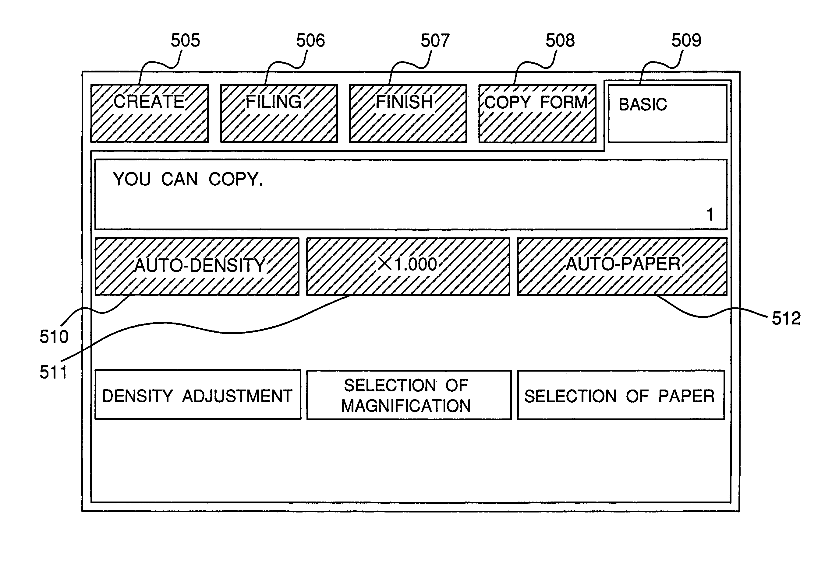
[0012]Therefore, a primary object of the present invention is to provide an image forming apparatus which allows an user to readily know in what operational mode or condition the apparatus is currently placed even though the user is not accustomed to operating the apparatus.
[0013]Another object of the present invention is to provide an image forming apparatus capable of displaying various pieces of information including user identification information without requiring an increase of the display space.

Problems solved by technology

However, a large number of characters and numerals indicating set information, status of the copying machine, and the like are required to be displayed on the screen having a limited display space.
Thus, it is difficult to secure a space for displaying the department code, the ID number, and / or the job number in the screen.
Therefore, it is difficult for people not accustomed to operating the copying machine to readily find where information of the department or the job is displayed on the screen.
However, people not accustomed to operating the composite apparatus are likely to be unaware of the LED 921, thus having difficulty in finding the selected function.
Thus, it is difficult for a user to intuitively know which of the basic function-related copy modes and the applied function-related copy modes have been set or whether neither the basic function-related copy modes nor the applied function-related copy modes have been set or not.
However, the existing copying machine is not designed so that the user can intuitively know which of the programs has been called.
However, again, the existing machines are not designed such that the user readily know the presence and contents of a copy mode set automatically in relation to a copy mode set by the user.

Method used


Image

  • Image forming apparatus having a display changeable in color according to operational mode
  • Image forming apparatus having a display changeable in color according to operational mode
  • Image forming apparatus having a display changeable in color according to operational mode

Examples


first embodiment

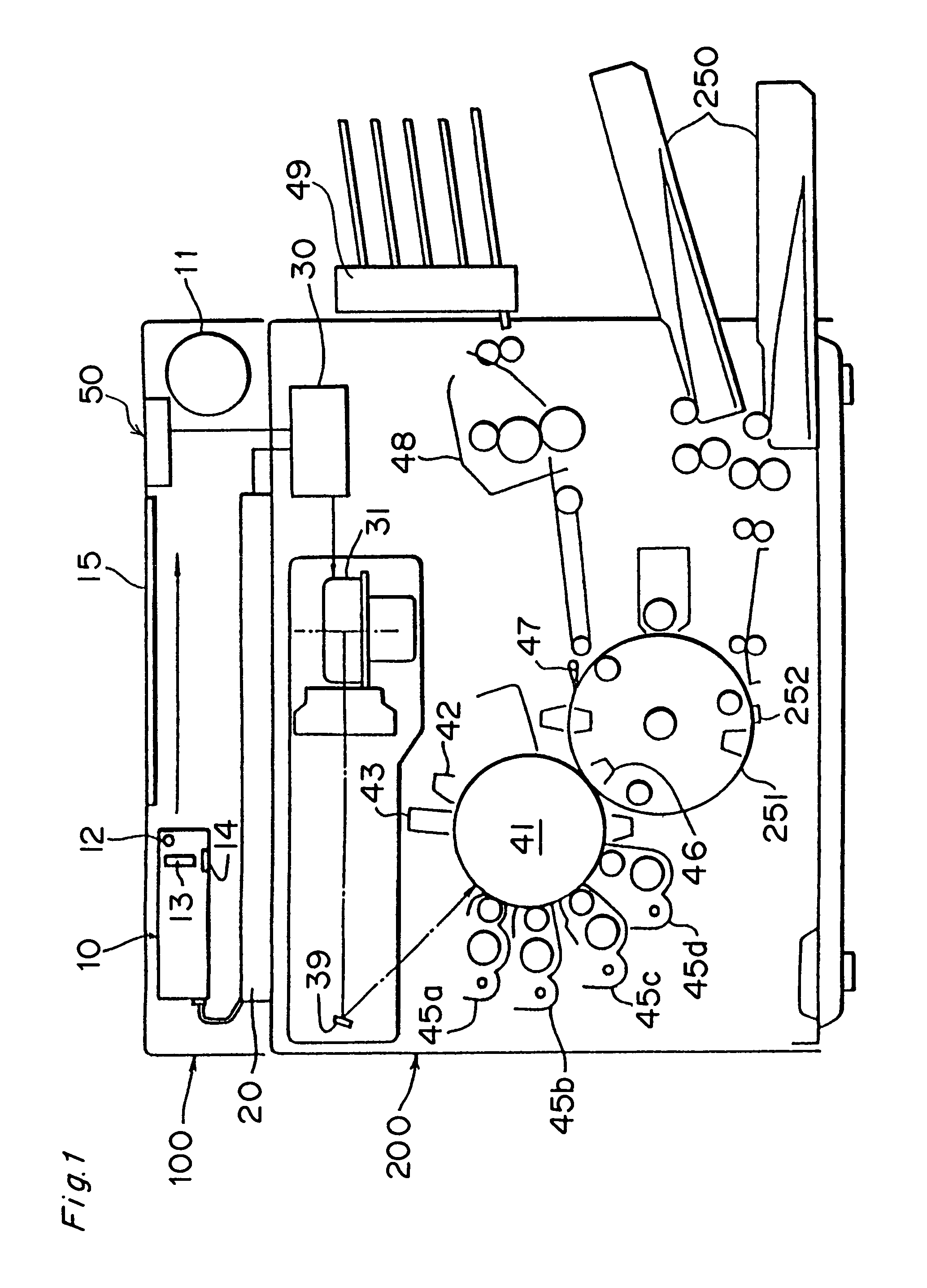
[0065]FIG. 1 is a schematic sectional view showing a digital color copying machine according to a first embodiment of the present invention.

[0066]The digital color copying machine is comprised of an image reading section 100 for reading an image of a document and an image forming section 200 reproducing the image read by the image reading section 100.

[0067]A scanner 10 in the image reading section 100 has an exposure lamp 12 for irradiating a document, a rod lens array 13 for condensing light reflected by the document, and a contact type CCD color image sensor 14 for converting condensed light into electric signals. When the document is read, the scanner 10 is driven by a motor 11 and moves in a direction (sub-scanning direction) shown by an arrow, thus scanning the document placed on a platen 15. The image of the document exposed to the exposure lamp 12 is photoelectrically converted by the image sensor 14. Multi-valued electric signals of the three colors of R, G, and B obtained b...

second embodiment

[0094]FIG. 10 schematically shows a construction of a digital copying machine 101 according to the second embodiment of the present invention. The digital copying machine 101 has a copying function, a FAX (facsimile) function, and a printing function, so that the machine 101 will be referred to as a composite apparatus below.

[0095]The composite apparatus 101 has an image reading section 102, a printing section 103 for printing image data, thus serving as an image forming section, a FAX modem 104 for sending image data to those located at remote places and receiving image data therefrom, an operation panel section 105 for allowing the user to enter various settings including setting of the copying function and the FAX function, and a controller 106 receiving data from a personal computer (hereinafter referred to as merely computer) PC.

[0096]FIG. 11 is a view showing a surface of the operation panel section 105 seen from the front. On the surface of the panel section 105, there are pr...

third embodiment

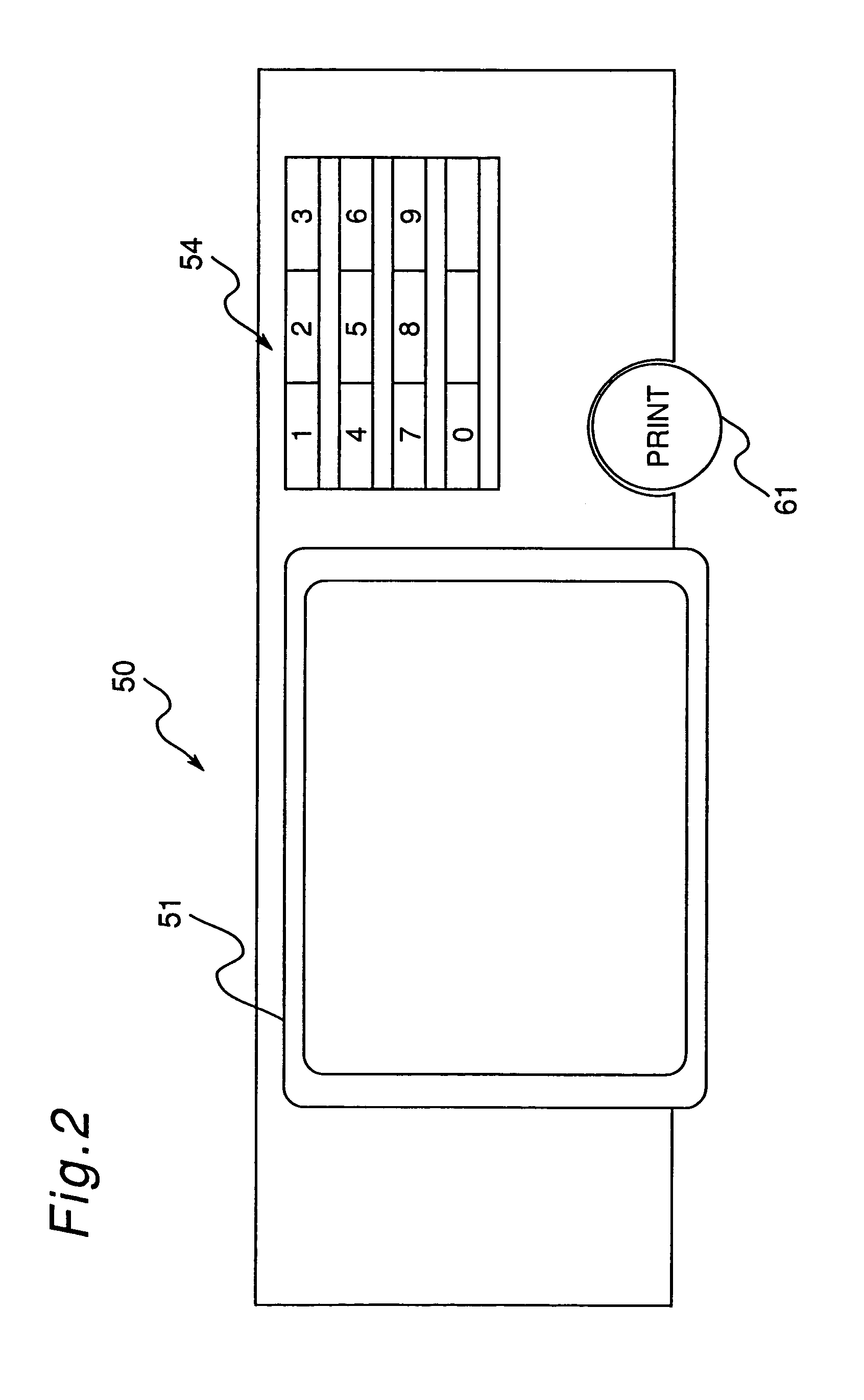
[0115]A digital color copying machine of a third embodiment of the present invention will be described below with reference to FIGS. 16–27. A schematic sectional view of the digital color copying machine of the third embodiment of the present invention, a front view of the surface of an operation panel section, and a block diagram of a control system in the operation panel section are similar to those of the digital color copying machine of the first embodiment of the present invention shown in FIGS. 1, 2 and 3, respectively. Accordingly, description of the same parts of the third embodiment as those of the first embodiment is omitted and parts of the third embodiment different from those of the first embodiment are described mainly, using the reference numerals and symbols which are used in the first embodiment.

[0116]As described below, the RAM 58 of the third embodiment stores various data of: (i) copy modes to be set by a user and copy modes to be automatically set based thereon,...


PUM


Abstract

An image forming apparatus has an image forming section for forming an image in a plurality of operational modes and a display device for executing display in a plurality of colors. Color information corresponding to the plurality of operational modes is stored in a memory. A CPU reads color information corresponding to an operational mode to be executed from the memory and controls the color to be displayed on the display device.

Description

[0001]This application is based on application(s) Nos. 9-261582, 9-283625 and 9-283627 filed in Japan, the contents of which are hereby incorporated by reference.BACKGROUND OF THE INVENTION[0002]The present invention relates to an image forming apparatus embodied as, e.g., a copying machine, a facsimile (FAX) apparatus, a printer or a composite apparatus having two or all of a copying function, a facsimile function, and a printing function.[0003]Recently, copying machines in which copy modes (i.e., copying conditions), such as the number of copies, are manageable for each of different people and departments using the copying machine are in wide use. In such a copying machine, identification information such as an ID number or a password is registered. A user can be allowed to use the copying machine when the user enters through an operation panel of the machine or from an external apparatus the same identification information as that registered.[0004]Further, there are also widely s...

Claims


Application Information

Patent Timeline
IPC IPC(8): G06F13/00G06F3/12G06K15/00H04N1/00
CPCG06K15/00G06K15/005H04N1/00408H04N1/00411H04N1/32496H04N1/00416H04N1/00432H04N1/00466H04N1/00482H04N1/00413G03G15/502
Inventor TOYAMA, MASAMITAKEMOTO, MOTOMIYOSHIDA, AKINORIIKEDA, HIROAKIKATO, TOMOKAZUNATSUME, JUNKO
Owner MINOLTA CO LTD
Learn More