Image reading device

a technology of image reading and reading device, which is applied in the direction of article separation, thin material processing, printing, etc., can solve the problems of unstable sheet separating performance, increased number of components, and inability to provide highly efficient and precise sheet conveying system, etc., and achieves superior sheet separating performance.

Inactive Publication Date: 2006-08-08
CANON KK
View PDF31 Cites 27 Cited by
  • Summary
  • Abstract
  • Description
  • Claims
  • Application Information

AI Technical Summary

Benefits of technology

[0054]An object of the present invention is to provide an image

Problems solved by technology

Therefore, since it is very difficult to manage a positional relation between the separating piece 1102 and the separating roller 1101 and the spring state, there is a problem that sheet separating performance is unstable.
Therefore, it becomes necessary to disconnectably connect the drive of the discharging roller 1106 with the drive system of the sheet conveying device body, and there arises a problem that the highly efficient and precise sheet conveying system cannot be provided.
Furthermore, even if the highly efficient and precise sheet conveying system can be constituted, there is another problem that the number of components is increased and cost is also increased.
Moreover, there is a demand for means for removing the document from the device body when the reading operation of the device is abnormally stopped halfway.
In the image reading device in which the device body is compact and easily operable, however, it is difficult to dispose a large document base.
Here, first, assuming that the device body cannot recognize whether or not the attachable/detachable reading section is attached to the device body, in the operation of reading the sheet document while the detachable/attachable reading section is detached from the device body, the document is not conveyed onto the reading section, so that the image information cannot be read.
Moreover, the document conveying is performed while no reading section is disposed in the document conveying path, and there is a defect that improper conveying, and the like could be generated.
Moreover, when the reading section is detached from the device body, and power supply is turned on, there is a defect that the white reference data cannot be taken.
Moreover, assuming that the upper document guide is moved, the device body cannot recognize whether or not the document conveying path is opened, but the document conveying path is opened, by turning on the power supply, the white reference member itself is detached from the image reading device, or the reading document conveying path is opened.
In this case, exterior light enters the image reading face of the image reading device, which cases a defect that the white reference data cannot sufficiently be taken.
The cost increase of the device body cannot be avoided, which also causes a defect that the assembling property and compactness

Method used


Image

  • Image reading device
  • Image reading device
  • Image reading device

Examples


first embodiment

(a) First Embodiment

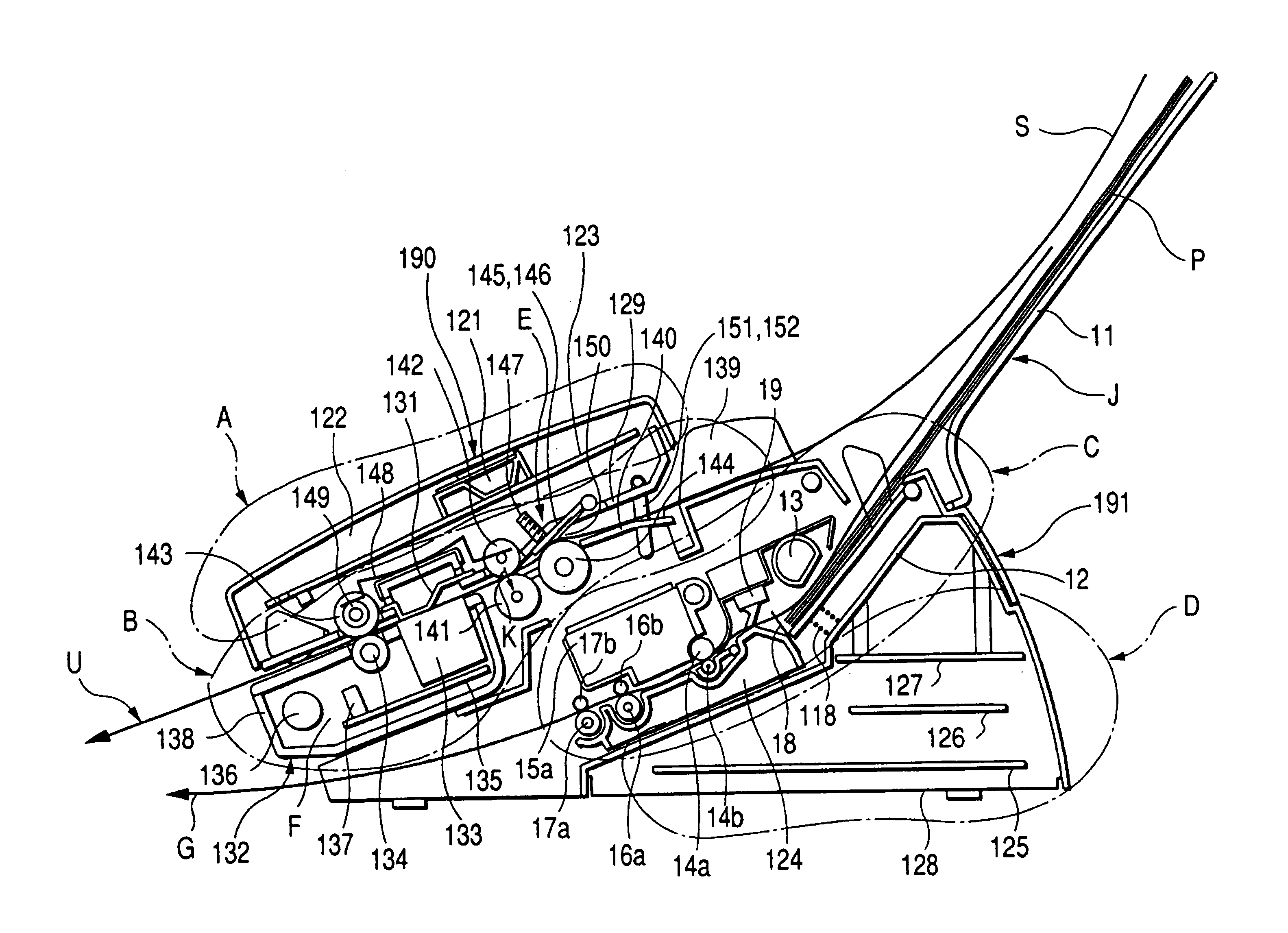
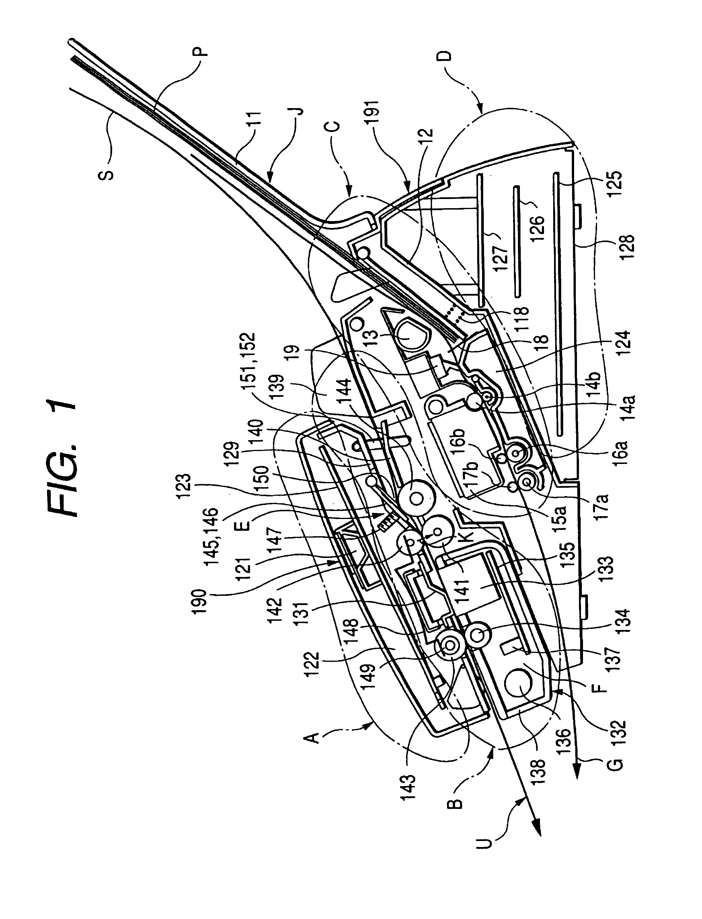
[0124]A facsimile device 191 provided with an attachable / detachable reading unit as one example of an image reading device 190 according to the present invention will be described with reference to FIG. 1.

[0125]The device has a layout of four sections: an operating section A; a reading section B; a recording section C; and a power supply section D in order from above.

[0126]Additionally, in FIG. 1, to facilitate the understanding of constitutions of the sections A to D, for convenience, the sections are surrounded by virtual lines, but they are not necessarily limited to the ranges surrounded by the virtual lines.

[0127]First, the operating section A will be described.

[0128]The operating section A comprises a panel cover 122 in which windows of keys for operating the functions of the facsimile device 191 and a liquid crystal display (LCD) 121 and a light emitting diode (LED) informing users of device states are arranged; an operation substrate 123 attached to the i...

second embodiment

(b) Second Embodiment

[0198]A second embodiment of the present invention will be described hereinafter with reference to the drawings.

[0199]FIG. 10 is a schematic sectional view of the facsimile device as the image reading device of the second embodiment of the present invention.

[0200]In FIG. 10, the device is provided with a document inserting port 21; a document bunch 22; a schematically shown document presence / absence detecting sensor 23; a separating roller 24; a separating piece 25; a separating piece pressing spring 26; an operation panel 27; keys 28 on the operation panel 27; a separated sheet of document 29; a document conveying path 210 of the document 29; feeding rollers 211a, 211b; a feeding roller pair 211 formed of feeding rollers 211a, 211b; a pressing spring 212 for the feeding and discharging rollers; a schematically shown document tip / rear end detecting sensor 213; a reading sensor (reading means) 214 which is an adhesion type image sensor; a white reference member 2...

third embodiment

(c) Third Embodiment

[0246]

[0247]An implementation of the image reading device of ink jet recording according to a third embodiment of the present invention will be described hereinafter with reference to the drawings. Additionally, for a first implementation, the application to the facsimile device will be described.

[0248]First, the schematic constitution of the facsimile device will be described with reference to FIGS. 15 and 17. In FIG. 15, character A denotes a reading section for optically reading the document; B denotes a recording section as an ink jet recording device; C denotes a recording sheet feeding section for separating stacked recording sheets and feeding the sheets to a recording unit; and D denotes a document feeding section for separating stacked document sheets and conveying them to a reading unit. On the other hand, in FIG. 17, E denotes an operating unit which operates functions, and which is opened during the jam handling of document S, the cleaning operation o...


PUM


Abstract

There is disclosed an image reading device, comprises a stacking section for stacking a document, a reading section for reading an image of the document, a separating section for separating the document stacked on the stacking section sheet by sheet, a conveying section for conveying the document separated by the separating section to the reading section and a discharging section for discharging the document to the outside of the device. In the device, sheet separating performance is enhanced. Additionally, the device body is reduced in cost and size, excellent reading operation can constantly be realized, and device assembling property is enhanced.

Description

BACKGROUND OF THE INVENTION[0001]1. Field of the Invention[0002]The present invention relates to an image reading apparatus having sheet conveying device.[0003]Moreover, the present invention relates to an image reading device, particularly to an image reading device, for example, which has a reading section detachably attached to a device body and an openable / closable operating section.[0004]Furthermore, the present invention relates to an image reading device, particularly to an image reading device which is provided, for example, with recording means for recording an image on a recording sheet, or a rolled sheet storage section for feeding the recording sheet to recording means, below separating means for conveying a document to reading means.[0005]Additionally, the present invention relates to an image reading device, particularly to an image reading device which is provided, for example, with a reading section for taking in an image of document, and which is applied to a facsim...

Claims


Application Information

Patent Timeline
IPC IPC(8): H04N1/40H04N1/00H04N1/107H04N1/12
CPCH04N1/00525H04N1/00541H04N1/00567H04N1/00588H04N1/00591H04N1/0062H04N1/00628H04N1/00631H04N1/00665H04N1/00602H04N1/121H04N1/107
Inventor TERASHIMA, HIDEYUKISASAI, KEIZOIWATA, NAOHIROMORINAGA, KAZUYUKIOBANA, KATSUMISUZUKI, YOSHIAKI
Owner CANON KK
Why Eureka
Try Eureka