Path search circuit, radio receiver and radio transmitter, utilizing a directional beam

a search circuit and radio receiver technology, applied in the direction of instruments, amplitude demodulation, transmission monitoring, etc., can solve the problems of deterioration of directional gain, interference components are not fully suppressed, and the reception quality is affected, so as to reduce the direction dependence of detection accuracy

Active Publication Date: 2006-08-08
PANASONIC CORP
View PDF15 Cites 23 Cited by
  • Summary
  • Abstract
  • Description
  • Claims
  • Application Information

AI Technical Summary

Benefits of technology

[0011]A path search circuit of the present invention is a path search circuit comprising: an orthogonal multi-beam forming section for multiplying a plurality of base band signals obtained by demodulating a plurality of radio-frequency signals received by a plurality of antennas respectively in a plurality of radio receiving sections by a first weight concerned with a plurality of mutually orthogonal directivities; a correlation operating section for correlation-operating outputs of the orthogonal multi-beam forming sectio

Problems solved by technology

The signal, to be received by a base station apparatus, suffers interference with various signals, causing the deterioration in reception quality.
However, in the conventional receiver employing the above configuration, in the case that there is an arrival of a mobile terminal (hereinafter, referred to as “desired user”) radio wave to be intentionally caught by the base statio

Method used


Image

  • Path search circuit, radio receiver and radio transmitter, utilizing a directional beam
  • Path search circuit, radio receiver and radio transmitter, utilizing a directional beam
  • Path search circuit, radio receiver and radio transmitter, utilizing a directional beam

Examples


embodiment 1

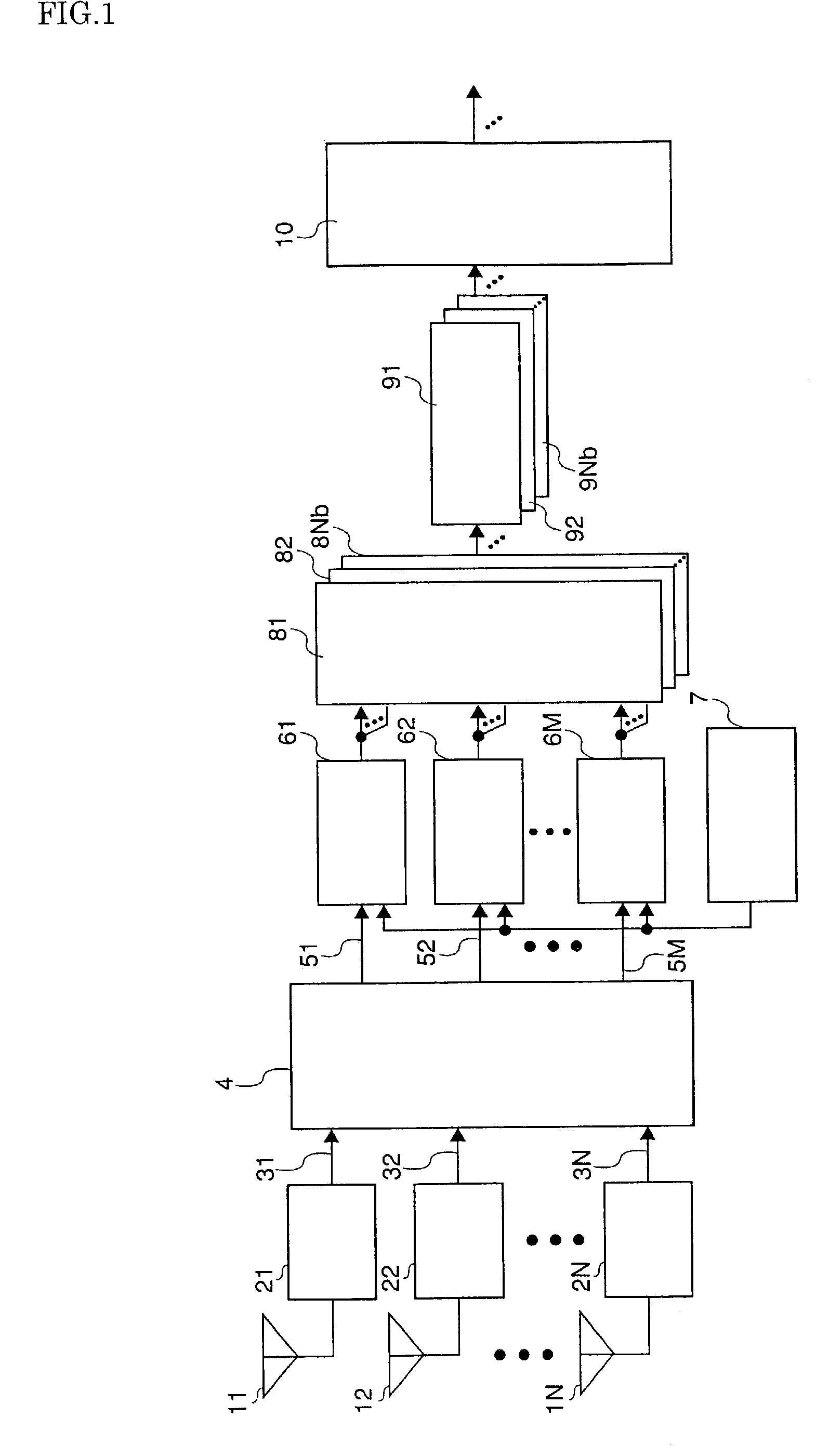
[0050]FIG. 1 is a block diagram showing a configuration of a path search circuit according to embodiment 1 of the invention. The path search circuit shown in FIG. 1 has antennas 11–1N for receiving radio-frequency signals, radio receiving sections 21–2N for carrying out radio-frequency amplification, frequency conversion, orthogonal detection and A / D conversion, in the order, on the radio-frequency signal received at the antennas 11–1N and generating base band signals 31–3N, an orthogonal multi-beam forming section 4 for multiplying a complex coefficient on the base band signals 31–3N obtained in the radio receiving sections 21–2N to thereby multiplying for a plurality (M in the number) of beam weights orthogonal one to another, a pilot-signal generating section 7 for generating a known signal (hereinafter, pilot signal) previously embedded in the reception signal, correlation operating sections 61–6M for correlation-operating the output of the orthogonal multi-beam forming section ...

embodiment 2

[0085]FIG. 8 is a block diagram showing a configuration of a path search circuit in embodiment 2 of the invention. The different part from embodiment 1 lies in that a beam selecting section 20 for selecting an output of the correlation operating sections 61–6M is added whereby the weight multiplying sections 81–8Nb carry out weight multiplication on the basis of an output thereof. In the below, explanation will be made mainly on the part different from embodiment 1. The radio-frequency signal received at the antennas 11–1N is subjected to radio-frequency amplification, frequency conversion, orthogonal detection and A / D conversion, in the order, in the radio receiving sections 21–2N provided on the antennas 11–1N, to form base band signals 31–3N that are to be inputted into the orthogonal multi-beam forming section 4. The orthogonal multi-beam forming section 4 multiplies a complex coefficient on the base band signal 31–3N obtained in the antenna element, thereby multiplying for a pl...

embodiment 3

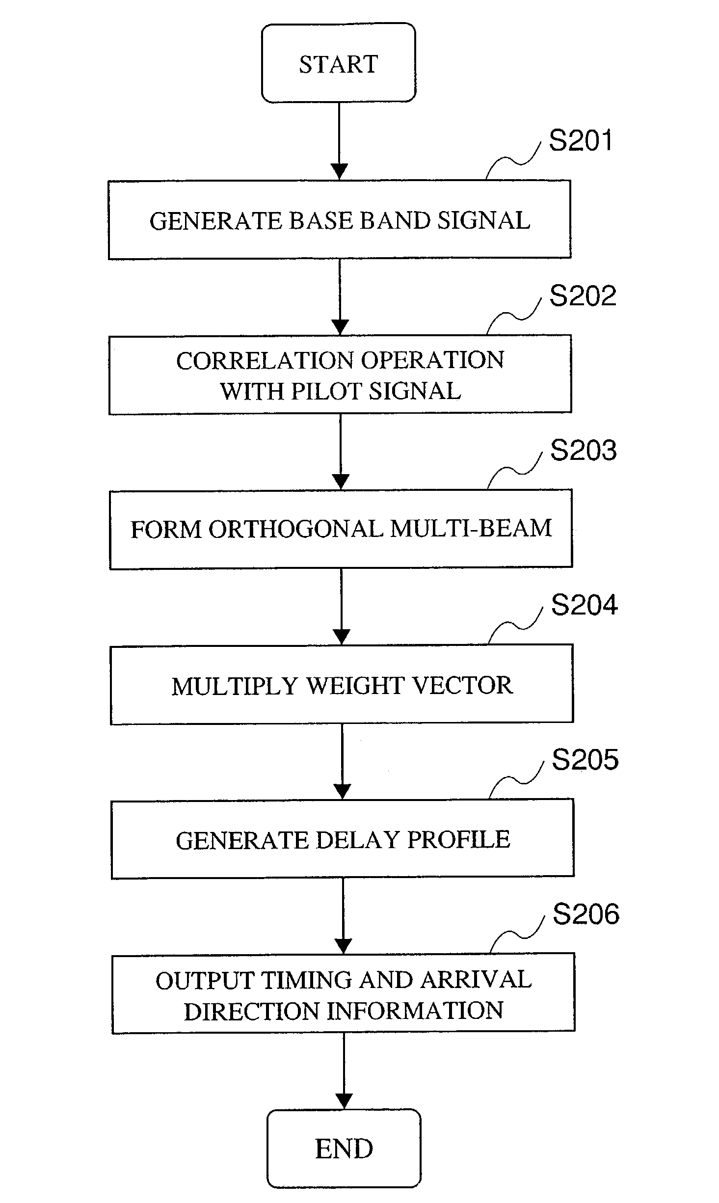
[0097]FIG. 9 is a block diagram showing a configuration of a path search circuit according to embodiment 3 of the invention. The different part from embodiment 1 lies in that there are provided correlation operating sections 611–61N for carrying out correlating operation, with a pilot signal, on the base band signals as outputs of the radio receiving sections 21–2N wherein an orthogonal multi-beam forming section 41 and weight multiplying sections 811–81N are provided for the correlation operating value outputs thereof. In the below, explanation will be made mainly on the part different from embodiment 1, by using FIGS. 9 and 10. FIG. 10 is a flowchart showing the operation of the path search circuit in embodiment 3 of the invention.

[0098]In the path search circuit shown in FIG. 9, the radio-frequency signal received at the antennas 11–1N is subjected to radio-frequency amplification, frequency conversion, orthogonal detection and A / D conversion, in the order, in the radio receiving...


PUM


Abstract

A path search circuit according to the present invention has an orthogonal multi-beam forming section 4 for directional reception with a plurality of orthogonal multi-beams orthogonal one to another, correlation-operating sections 61–6M for correlation-operating outputs of the orthogonal multi-beam forming section 4 with a known signal, weight multiplying sections 81–8Nb for multiplying the output of the correlation-operating section 61–6M by a weight converted into a beam space, delay profile generating sections 91–9Nb for generating delay profiles from the output signals of the weight multiplying sections 81–8Nb, and a path detecting section 10 for detecting a reception timing and arrival direction of arrival path from the delay profile. This path search circuit can enhance the accuracy of path direction detection by the use of a directional reception signal, and further reduce the direction dependence of path timing detection accuracy.

Description

FIELD OF THE INVENTION[0001]The present invention relates to a path search circuit, radio receiver and radio transmitter concerned with detection of a path direction and timing in a radio base station apparatus having antennas, such as array antennas, for use in a digital radio communication system.BACKGROUND OF THE INVENTION[0002]The signal, to be received by a base station apparatus, suffers interference with various signals, causing the deterioration in reception quality. There is known an adaptive array antenna as an art of suppressing the interference and receiving strongly only the signal arriving in a desired direction. In the adaptive array antenna, the weighting coefficient for multiplied on a reception signal (hereinafter, the weighting coefficient is referred to as “weight”) is adjusted to regulate the amplitude and phase for provision to the reception signal, thereby making it possible to receive strongly only the signal arriving in a desired direction.[0003]Meanwhile, t...

Claims


Application Information

Patent Timeline
IPC IPC(8): H04B1/00H04B15/00H01Q3/26H04B1/707H04B1/7113H04B1/7117H04B7/08H04B7/10H04B7/26H04W16/28H04W88/08
CPCH04B1/7113H04B7/086H04B1/7117
Inventor KISHIGAMI, TAKAAKIFUKAGAWA, TAKASHIYUDA, YASUAKITAKAKUSAKI, KEIJIMIYAMOTO, SHOJI
Owner PANASONIC CORP
Why Eureka
Try Eureka