Sound generating device for a dual bearing reel

a dual-beam reel and sound generation technology, which is applied in the direction of reels, applications, fishing, etc., can solve the problems of difficult to change the sound and resistance in accordance, the sound generation device will no longer provide resistance with respect to the rotation of the spool, and the sound generation device will not be possibl

Active Publication Date: 2006-08-15
SHIMANO INC +1
View PDF7 Cites 9 Cited by
  • Summary
  • Abstract
  • Description
  • Claims
  • Application Information

AI Technical Summary

Benefits of technology

[0008]It is an object of the present invention to allow the sound and resistance of a sound generating device for a dual bearing reel to be easily changed in accordance with the rotational direction.
[0010]With this sound generating device, when the operation member is moved to a position separated from the serrated member, the sounding member will be disposed in a release position in which the tip thereof is separated from the projections of the serrated member. When the sounding member is moved to a position near the serrated member, the sounding member will be disposed in a sound generation position in which the tip thereof can contact the projections. When the spool rotates in this state, the sounding member will be urged toward the center of the serrated member by the first urging member. Thus, the tip of the sounding member will repeatedly strike the projections. Resistance will be applied with respect to rotation, and the device will generate sound. In addition, when the spool rotates in the line releasing direction, the sounding member is further urged in a direction opposite the pivoting direction by the second urging member. Because the urging force will be stronger in the line winding direction, a larger rotational resistance will be applied and a louder sound will be generated. Here, by providing the second urging member that will urge the sounding member in the pivoting direction and the opposite direction, both a large rotational resistance can be applied and loud sounds can be generated when the rotational direction of the spool is the line release direction. Given this structure, sounds and resistance can be easily changed in accordance with the rotational direction.
[0012]A sound generating device for a dual bearing reel according to a third aspect of the present invention is the device set forth in the first or second aspect, in which the second urging member is a torsion coil spring that is wound around the outer periphery of the operation member. Further, a first end of the second urging member is engaged with the sounding member and a second end of the second urging member is engaged with the reel unit. The first end in contacts the sounding member when the sounding member is in the sound generation position, and separates from the sounding member when the sounding member is in the release position. In this configuration, the first end will be separated from the sounding member in the release position even if the second end of the second urging member is engaged with the reel unit, and thus the engagement structure of the second end will be simplified and there will be no impact on the operation of the operation member.
[0017]A sound generating device for a dual bearing reel according to an eighth aspect of the present invention is the device set forth in the seventh aspect, in which the angle formed by the engagement portion and the pawl portion is an acute angle. In this configuration, the engagement portion and the pawl portion project outward forming an acute angle therebetween. Thus, the sounding member is compact and the placement of the sounding member will be simplified.

Problems solved by technology

In addition, when the operation member is moved to the separated position, the sounding member will be disposed in a release position in which the tip thereof is separated from between the projections, and thus sound generation will not be possible.
As a result, the sound generating device will no longer provide resistance with respect to the rotation of the spool.
However, with the aforementioned conventional sound generating device, it is difficult for the sound and resistance to be changed in accordance with the direction of rotation because, as noted above, the sounding member is urged by the same urging member toward the axial center of the spool shaft when the tip of the sounding member is disposed between the projections.

Method used


Image

  • Sound generating device for a dual bearing reel
  • Sound generating device for a dual bearing reel
  • Sound generating device for a dual bearing reel

Examples


Embodiment Construction

[0030]Selected embodiments of the present invention will now be explained with reference to the drawings. It will be apparent to those skilled in the art from this disclosure that the following descriptions of the embodiments of the present invention are provided for illustration only and not for the purpose of limiting the invention as defined by the appended claims and their equivalents.

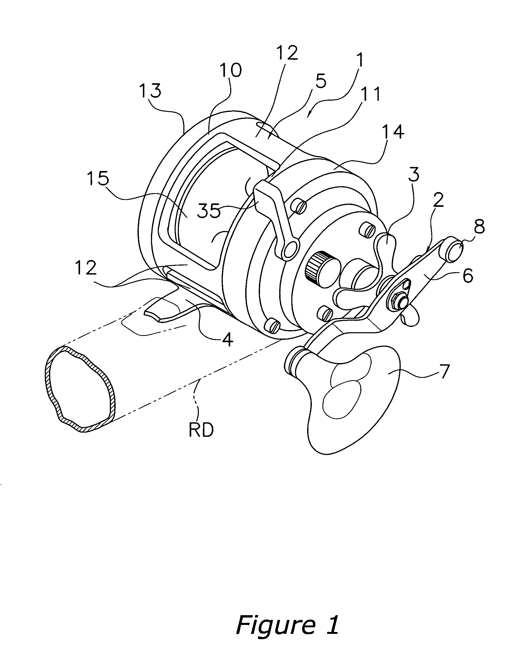
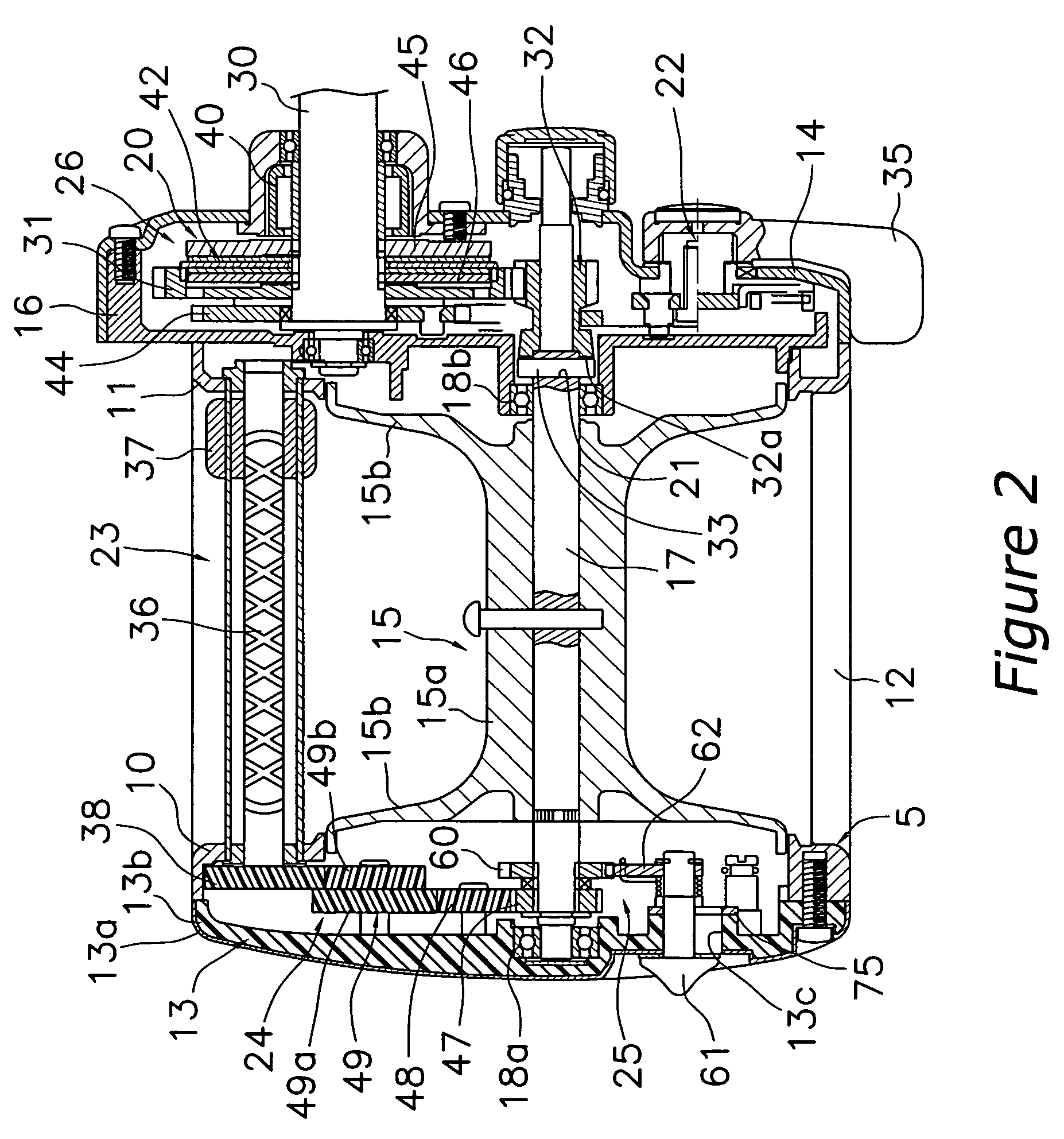
[0031]FIG. 1 illustrates a medium sized round type of dual bearing reel in accordance with a preferred embodiment of the present invention. The dual bearing reel includes a reel unit 1, a handle assembly 2, and a star drag 3. The handle assembly 2 is provided to rotate a spool 15 that is disposed sideways in the reel unit 1. The star drag 3 is disposed on the handle assembly 2 side of the reel unit 1. The spool 15 is rotatively mounted on the reel unit 1. The reel unit 1 is mounted on a fishing rod RD via a rod attachment leg 4. As shown in FIG. 2, the reel unit 1 includes a frame 5 a first cover 1...


PUM


Abstract

A sound generating mechanism of a dual bearing reel generates sound by the rotation of a spool, and includes a serrated member, an operation member, a sounding member, a first urging member, and a second urging member. The serrated member includes projections and rotates with the spool. The operation member can come into contact and be separated from the serrated member. The sounding member is pivotably movable in accordance with movement of the operation member between a sound generation position and a release position. The first urging member urges the sounding member toward the rotational center of the serrated member when the sounding member is in the sound generation position. While the sounding member is in the sound generation position, the second urging member applies a greater urging force to the sounding member when the spool rotates in the line-releasing direction than when the spool rotates in the line-winding direction.

Description

BACKGROUND OF THE INVENTION[0001]1. Field of the Invention[0002]The present invention relates to a sound generating device. More specifically, the present invention relates to a sound generating device for a dual bearing reel that generates sound by the rotation of a spool to wind line, the spool being rotatively mounted on a reel unit of the dual bearing reel.[0003]2. Background Information[0004]Known examples of a sound generating device for a dual bearing reel include a sound generating device that is linked to the rotation of the spool, generates sound, and applies resistance to the rotation of the spool. A conventional sound generating device includes a serrated member, an operation member, a sounding member, and an urging member. The serrated member is non-rotatively mounted on a spool shaft. The operation member is mounted to a reel unit and can be moved to contact and to separate from the serrated member. The sounding member that oscillates via the rotation of the serrated m...

Claims


Application Information

Patent Timeline
Patent Type & Authority Patents(United States)
IPC IPC(8): A01K89/01A01K89/015
CPCA01K89/015A01K89/0178A01K89/045
Inventor MORIMOTO, SHINICHIMARIMUTHU, MAHIMAI DAS A/L
Owner SHIMANO INC
Why Eureka
Try Eureka