Method for producing a lift and a horizontal thrust

a technology of lifting force and horizontal thrust, which is applied in the field of aerodynamics of flying apparatuses, can solve the problems of significantly reducing the efficiency of this method low efficiency of producing lifting force, so as to reduce the radius of circumference, reduce the speed, and reduce the effect of production efficiency

Inactive Publication Date: 2006-08-15
AKARO ANDREY IGOREVICH +3
View PDF7 Cites 9 Cited by
  • Summary
  • Abstract
  • Description
  • Claims
  • Application Information

AI Technical Summary

Benefits of technology

[0005]A disadvantage of this known method is that it has rather low efficiency of producing a lifting force because the cross-sections of the vanes have different velocities relative to air, the lower the radii of circumferences described by these cross-sections, the lower the velocity. As a result, a surface distribution of the aerodynamic force on the vanes appears to be non uniform (close to a square) which significantly reduces the efficiency of this method of producing a lifting force.
[0006]As the basis of the invention, an objective of finding a method of producing a lifting force and a horizontal thrust by aerodynamic surfaces is presented, in which a distribution of aerodynamic forces along aerodynamic surfaces which is close to a uniform is provided, that leads to high efficiency of producing both a lifting force and a horizontal thrust.

Problems solved by technology

A disadvantage of the known method is its rather low efficiency of production of a lifting force because the cross-sections of the vanes have different velocities relative to air, the lower the radii of circumferences described by these cross-sections, the lower the speed.
As a result, a surface distribution of the aerodynamic force on the vanes appears to be non uniform (close to a square), which significantly reduces the efficiency of this method of producing the lifting force.
A disadvantage of this known method is that it has rather low efficiency of producing a lifting force because the cross-sections of the vanes have different velocities relative to air, the lower the radii of circumferences described by these cross-sections, the lower the velocity.
As a result, a surface distribution of the aerodynamic force on the vanes appears to be non uniform (close to a square) which significantly reduces the efficiency of this method of producing a lifting force.

Method used


Image

  • Method for producing a lift and a horizontal thrust
  • Method for producing a lift and a horizontal thrust
  • Method for producing a lift and a horizontal thrust

Examples


Embodiment Construction

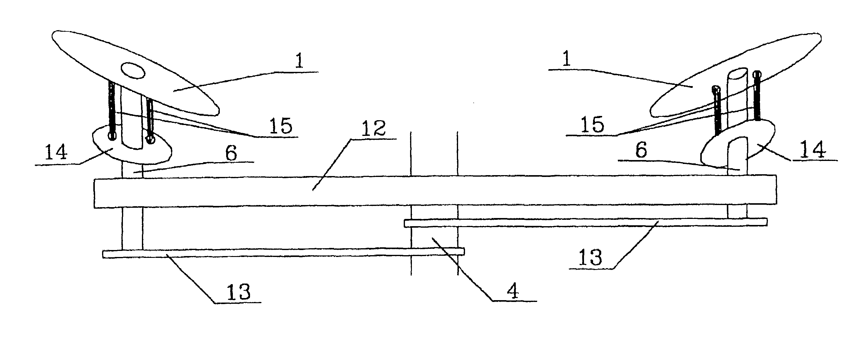
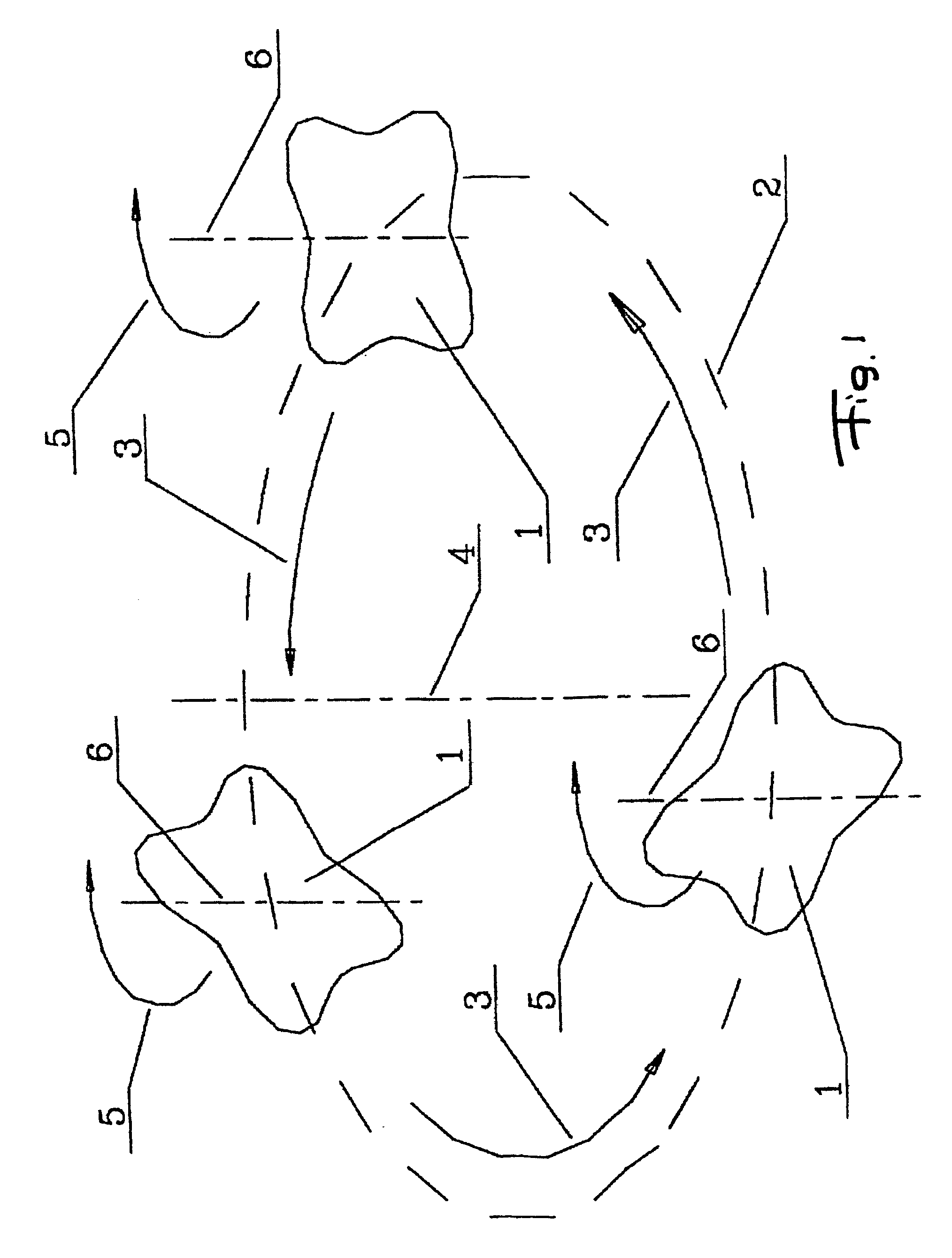
[0008]The rotation of each aerodynamic surface synchronously with the movement along a circumference in an opposite direction relative to the axis of rotation that is parallel to the axis of rotation along the circumference with angular speed equal to angular speed of the movement along the circumference, provides a rectilinear (without rotation) movement of the aerodynamic surface relative to air, which provides a production of a uniform distribution of the aerodynamic forces along an aerodynamic surface, leading to a high efficiency of production of the lifting force.

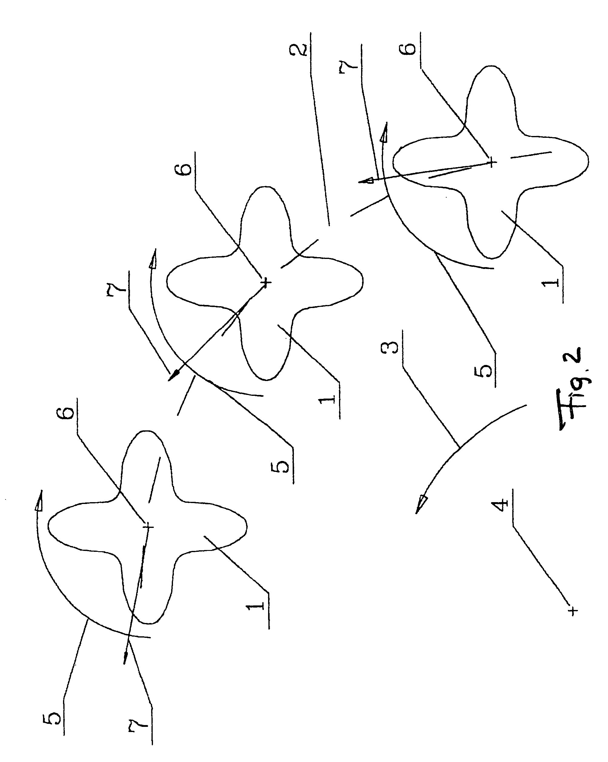
[0009]Performing of oscillations of each aerodynamic surface synchronously with their rotation relative to the mutually perpendicular axes, that are perpendicular to the axis of the movement of the aerodynamic surface along the circumference, provides simultaneously with the lifting force, the production of a horizontal thrust.

[0010]FIG. 1 shows a scheme of production of a rectilinear movement of aerodynamic surfaces;...


PUM


Abstract

A method of producing a lifting force and a horizontal force by aerodynamic surfaces includes the steps of moving aerodynamic surfaces along a circumference and providing their oscillations; rotating each of the aerodynamic surfaces synchronously with the movement along the circumference, in a direction which is opposite to it, relative to an axis of rotation which is parallel to an axis of the movement along the circumference, with an angular speed which is equal to an angular speed of the movement along the circumference, and performing oscillations of each of the aerodynamic surfaces synchronously with a rotation relative to mutually perpendicular axes located correspondingly in two mutually perpendicular planes which intersect along an axis of rotation of the aerodynamic surfaces, wherein one of them passes through an axis of the movement along the circumference and the axis of rotation.

Description

BACKGROUND OF THE INVENTION[0001]The invention relates to aerodynamics of flying apparatuses and represents a method of producing a lifting force and a horizontal thrust by aerodynamic surfaces, that are driven in movement by a lifting-pulling propulsion device of a flying apparatus.[0002]A method of producing a lifting force and a horizontal thrust by a vane-type carrying screw of a helicopter is known, which includes movement of vanes along a circumference and their oscillation around a longitudinal axis (A. M. Volodko “Helicopter—a Worker and a Soldier”, M. Publishing House DOSAAF USSR, 1984, pages 82–83, FIG. 24).SUMMARY OF THE INVENTION[0003]A disadvantage of the known method is its rather low efficiency of production of a lifting force because the cross-sections of the vanes have different velocities relative to air, the lower the radii of circumferences described by these cross-sections, the lower the speed. As a result, a surface distribution of the aerodynamic force on the ...

Claims


Application Information

Patent Timeline
Patent Type & Authority Patents(United States)
IPC IPC(8): B64C27/08B64C27/605B64C39/08B64C39/00
CPCB64C27/08B64C39/006B64C27/605
Inventor AKARO, ANDREY IGOREVICHDENISOV, ANATOLY ALEKSEEVICHZELINSKY, ANATOLY MIKHAILOVICHMEDVEDEV, MIKHAIL MIKHAILOVICH
Owner AKARO ANDREY IGOREVICH
Why Eureka
Try Eureka