Articulated support with lateral movement for high-voltage or medium-voltage electrical plant

a technology of articulating support and electrical plant, which is applied in the direction of machine support, movable shelf cabinet, dismountable cabinet, etc., can solve the problems of long process, complicated and difficult process, and interference of breaker

Inactive Publication Date: 2006-08-15
ALSTOM TECH LTD
View PDF5 Cites 28 Cited by
  • Summary
  • Abstract
  • Description
  • Claims
  • Application Information

AI Technical Summary

Benefits of technology

[0012]The support according to the invention has no separate parts that have to be demounted, requires no major additional plant, and allows costly electrical plant weighing several tons to be moved safely.

Problems solved by technology

At present, demounting the circuit-breaker interferes greatly with the operation of the electrical substation in which the plant shown in FIG. 1 is installed, as it implies disconnecting at least one of the two overhead lines and demounting the bushing-disconnector-framework assembly on the side that is disconnected, which is a long, complex and difficult process.

Method used


Image

  • Articulated support with lateral movement for high-voltage or medium-voltage electrical plant
  • Articulated support with lateral movement for high-voltage or medium-voltage electrical plant
  • Articulated support with lateral movement for high-voltage or medium-voltage electrical plant

Examples


first embodiment

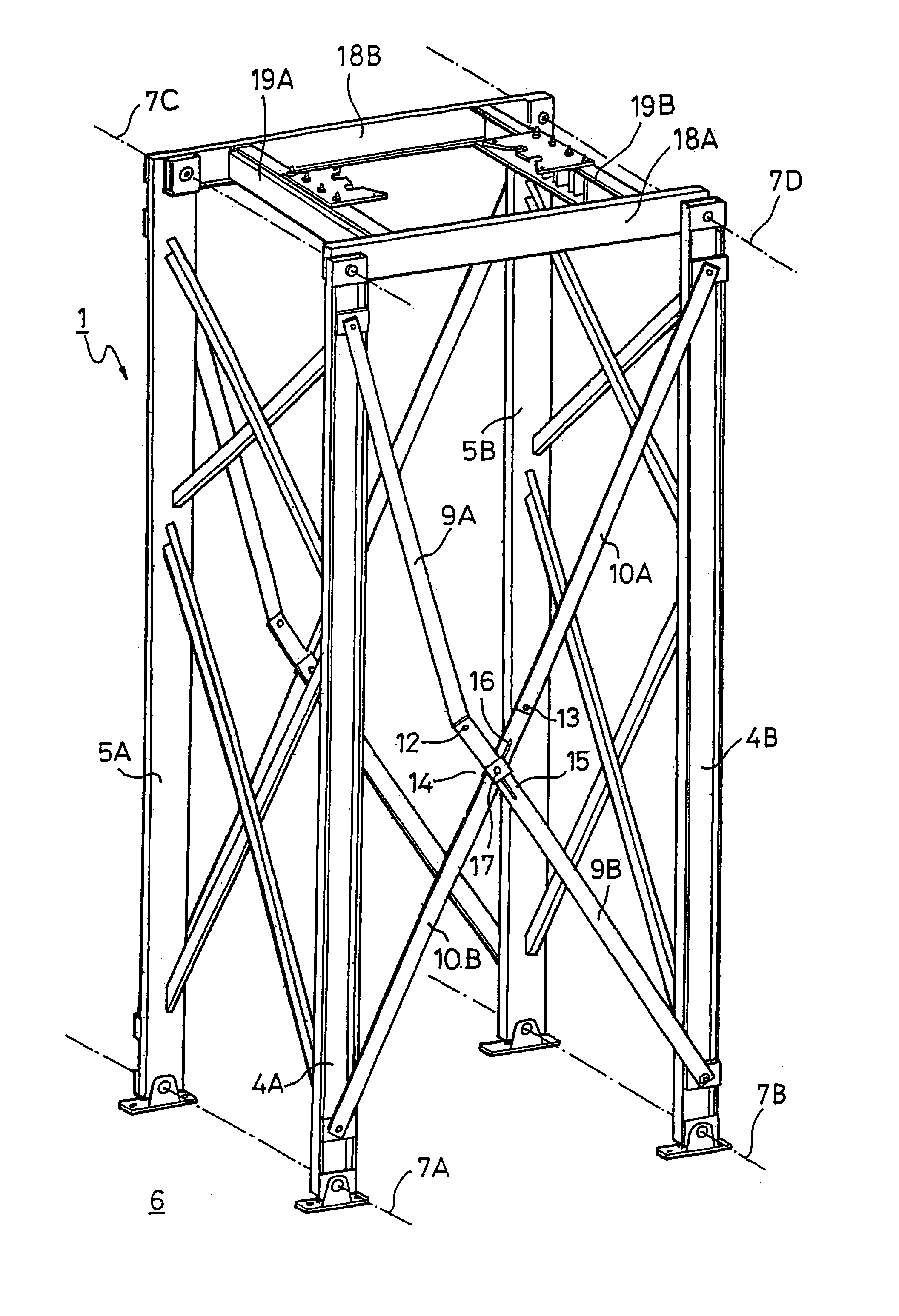
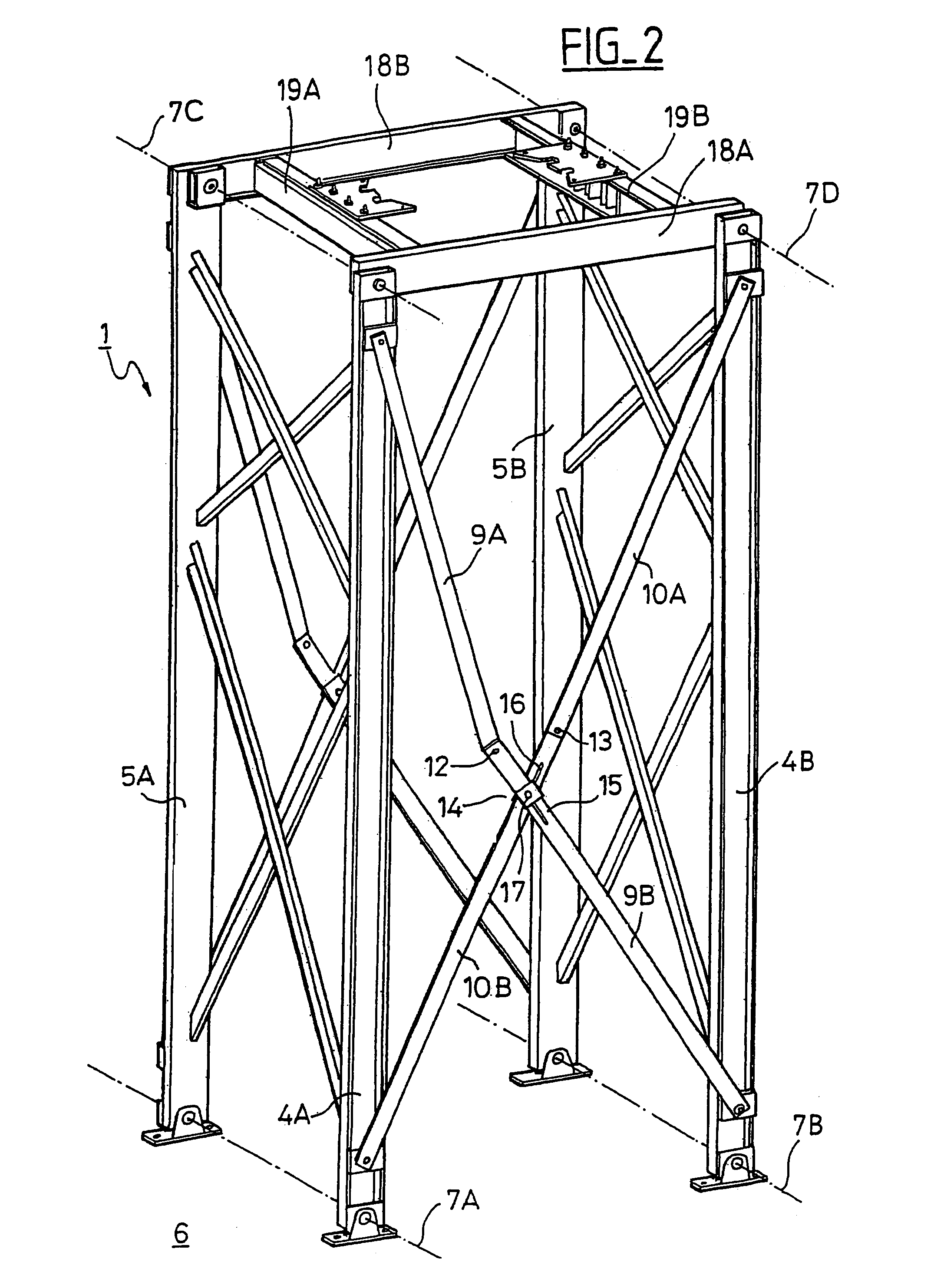
[0032]FIGS. 2 to 4 show the invention.

[0033]A support 1 for high-voltage or medium-voltage electrical plant comprises four substantially vertical columns 4A, 4B, 5A, 5B placed on a horizontal support surface 6, for example the ground.

[0034]The ends of the columns 4A, 4B, 5A, 5B resting on the ground are articulated about horizontal axes 7A, 7B.

[0035]The columns are connected in pairs by four crossmember assemblies, the two lateral crossmember assemblies shown in FIG. 2 being rigidly connected to the corresponding columns 4A and 5A, 4B and 5B and each consisting of crossing crossmembers that are rigidly connected together. One of said lateral crossmember assemblies is adapted to provide sufficient space for one end of a connection 8 to the adjacent shielded component 3 in the FIG. 1 application example.

[0036]The other two crossmember assemblies, one at the front and one at the rear, are symmetrical with respect to the vertical plane of symmetry of the support, and for simplicity only...

second embodiment

[0049]FIGS. 5 and 6 show the invention.

[0050]The second embodiment differs from the previous embodiment only in the design of the opposite crossmember assemblies, which are all that is described hereinafter.

[0051]The front and rear crossmember assemblies are symmetrical with respect to the vertical plane of symmetry of the support and for simplicity only the front assembly is described and its components identified by reference numbers here.

[0052]That assembly, disposed between the two columns 4A and 4B, comprises two crossing crossmembers 9′ and 10′ connected together non-rigidly. They are advantageously connected at their crossing point by a slotted connecting arrangement of the same type as the connection arrangement 14 shown in FIG. 2. The ends of the crossmembers 9′ and 10′ are articulated to the corresponding columns 4A, 4B to rotate about horizontal axes and a horizontal top crossmember 18A has its ends articulated to the corresponding two columns 4A, 4B to rotate about horiz...

third embodiment

[0059]the invention is described with reference to FIGS. 7 and 8.

[0060]This third embodiment differs from the previous embodiments only in the design of the opposite crossmember assemblies, which are all that is described hereinafter.

[0061]The front and rear crossmember assemblies are symmetrical with respect to the vertical plane of symmetry of the support and for simplicity only the front assembly is described and its components identified by reference numbers here.

[0062]That assembly, disposed between the two columns 4A and 4B, comprises two crossing crossmembers 9′ and 10″ connected together non-rigidly. They are advantageously connected at their crossing point by a slotted connecting arrangement of the same type as the connecting arrangement 14 shown in FIG. 2. The ends of the crossmembers 9″, 10″ are articulated to the corresponding two columns 4A, 4B to rotate about horizontal axes and a top horizontal crossmember 18A likewise has its ends articulated to the corresponding two...


PUM


Abstract

A support for high-voltage or medium-voltage electrical plant comprises four columns placed on a support surface and connected in pairs by crossmember assemblies. The columns are each articulated to rotate about a first horizontal axis at their end resting on the support surface and about a second horizontal axis on a top crossmember at their other end. The first and second axes are parallel. Two opposite crossmember assemblies allow the two columns connected by one or the other of these two assemblies to move in a stable manner in their rotation plane.

Description

BACKGROUND OF THE INVENTION[0001]1. Field of the Invention[0002]The present invention relates to an articulated support with lateral movement for high-voltage or medium-voltage electrical plant.[0003]To be more precise, it relates to a support for high-voltage or medium-voltage electrical plant comprising four columns placed on a support surface and connected in pairs by four assemblies of crossmembers.[0004]2. Description of the Prior Art[0005]This kind of support is used in shielded electrical plant housed in a metal enclosure, as shown in FIG. 1.[0006]Such plant includes a shielded horizontal circuit-breaker 2 connected at each of its two ends by way of a connecting compartment 8 to a shielded disconnector 3. The connecting compartment 8, carrying a toroidal current transformer 6, is closed in a manner known in the art by insulative cones. An overhead line bushing 11 is mounted on top of each disconnector 3 which, together with the bushings and ancillary plant, are supported by a...

Claims


Application Information

Patent Timeline
Patent Type & Authority Patents(United States)
IPC IPC(8): A45D19/04H02B3/00
CPCH02B3/00
Inventor CHAVOT, MICHELHABERT, JEAN LOUIS
Owner ALSTOM TECH LTD
Why Eureka
Try Eureka