Surgical instrument

a surgical instrument and a technology for surgical instruments, applied in the field of surgical instruments, can solve the problems of insufficient degree of articulation freedom, difficult to divert the previously-described surgical instrument for suturing and ligating, and difficult to turn the tool section and approach it to a target site, etc., and achieves excellent operability and durability. , the effect of easy execution

Inactive Publication Date: 2006-08-15
OLYMPUS CORP
View PDF32 Cites 219 Cited by
  • Summary
  • Abstract
  • Description
  • Claims
  • Application Information

AI Technical Summary

Benefits of technology

[0016]It is an object of the present invention to provide a surgical instrument with its excellent operability and durability, in which, while a single thumb and fingers other than the thumb are engaged with a manipulating section, a tool section can be articulated in an arbitrary direction relative to an insert section with such one hand, and tissue suturing / ligating manipulation can be easily executed by opening / closing the tool section.

Problems solved by technology

Thus, in particular, when a complicated manipulation for suturing / ligating tissues is achieved, the degree of freedom for articulating is insufficient.
However, while a single thumb and fingers other than the thumb are hooked on the manipulating section, it is difficult to turn the tool section and approach it to a target site by manipulation using the same one hand and to close and open the tool section at the target site.
Thus, it is difficult to divert the previously-described surgical instrument for suturing and ligating.
In actuality, there does not exist a surgical instrument suitable for suturing / ligating, the surgical instrument being capable of being articulated in an arbitrary direction and being capable of being opened / closed by one hand.
Thus, in fact, the effective width of the manipulating section side member cannot be set to a necessary and sufficient value.
In addition, an articulating torque generated by articulating of the manipulating section cannot be sufficiently obtained.
As a result, the required opening / closing gripping force and direct manipulation may be degraded.
As a result, there is a problem that the insert section is increased in diameter.
When the link is long, an error easily occurs between an articulating manipulation quantity of the manipulating section and articulating movement quantity of the tool section due to slackness of the link itself.
A general problem in the previously-described prior art is that, when the tool section is set into the desirable articulating state by articulating the manipulating section, if a surgeon turns a manipulating section excessively, or if a surgeon articulates a manipulating section with an excessive force, the tool section may be deformed or destroyed so that a normal operation may be failed.
Thus, the suture thread is hooked on the step, and there is a possibility that smooth ligating manipulation is inhibited.

Method used


Image

  • Surgical instrument
  • Surgical instrument
  • Surgical instrument

Examples


first embodiment

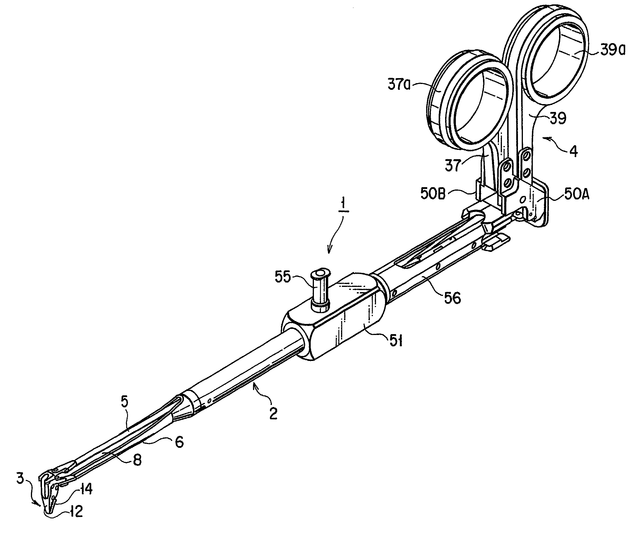
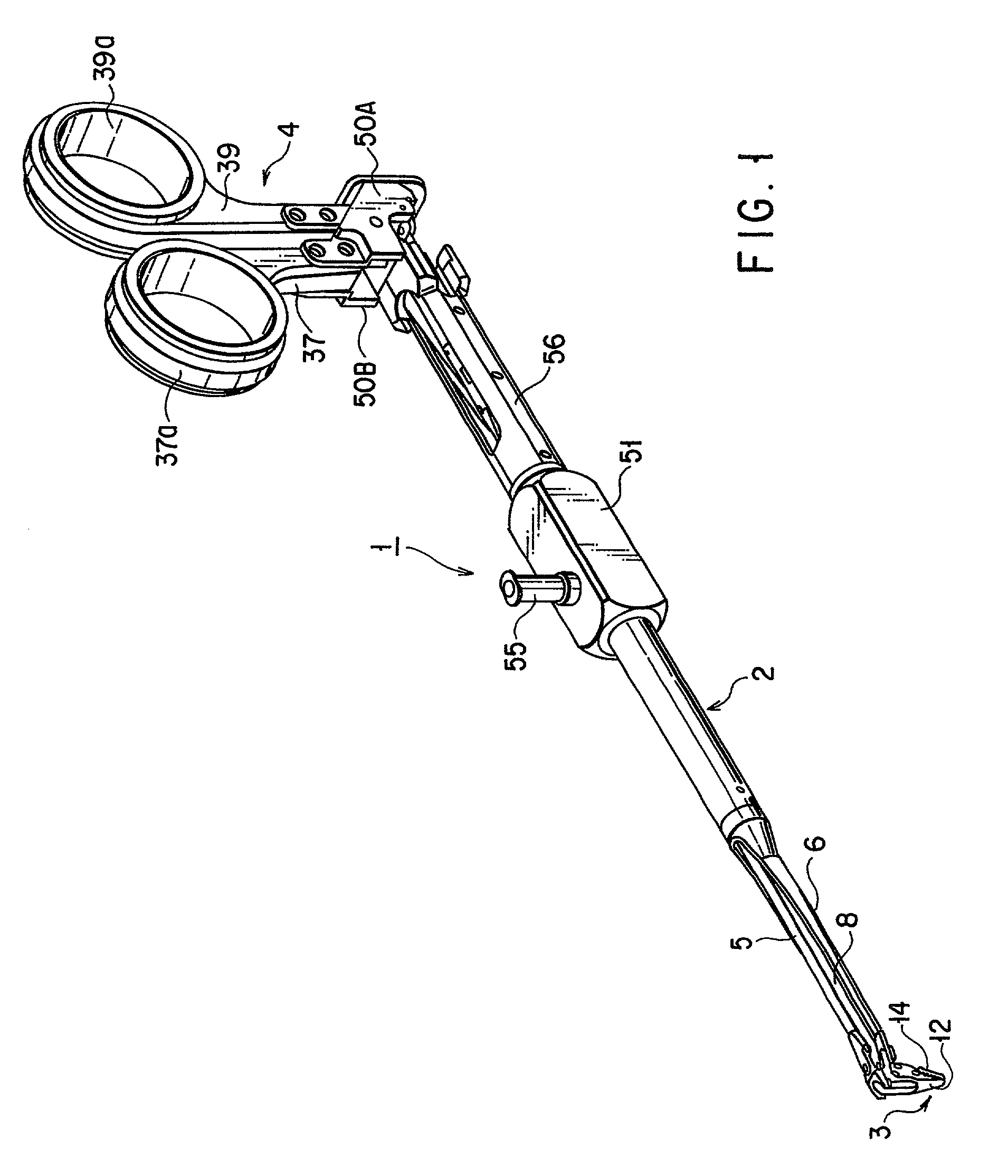
[0086]FIG. 1 to FIG. 16B show the present invention. As shown in FIG. 1, a surgical instrument 1 according to the present invention is composed of: an insert section 2; a tool section 3 provided at a distal end section of the insert section 2; and a manipulating section 4 provided at a proximal end section of the insert section 2.

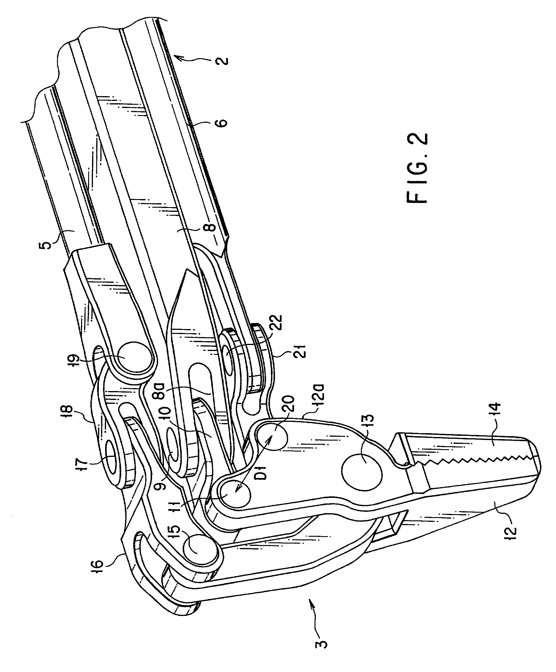
[0087]As shown in FIG. 2 to FIG. 6, a first drive rod 5 configuring an opening / closing link mechanism that consists of a convergent bar and a second drive rod 6 and a third drive rod 7 each configuring an articulating link mechanism are inserted into the insert section 2 in a parallel or substantially parallel to each other. The first drive rod 5 is disposed eccentrically at one side of the longitudinal center axis of the insert section 2 (upwardly in the present embodiment). The second and third drive rods 6 and 7 are disposed in a transversely symmetrical manner (downwardly in the present embodiment) eccentrically at the opposite side of the first drive r...

second embodiment

[0115]FIG. 17 to FIG. 24 show the present invention. The present embodiment is directed to a modified example of the first embodiment. Like constituent elements common to those of the first embodiment are designated by like reference numerals. A detailed description thereof is omitted here.

[0116]A description of a manipulating section 4 according to the present embodiment will be given here. As shown in FIG. 17 and FIG. 18, even in a proximal end section of the insert section 2, a first drive rod (long side link) 5 is disposed eccentrically upwardly of the axial center of the insert section 2. As shown in FIG. 19, the second and third drive rods (long side links) 6 and 7 are disposed in a transversely symmetrical manner downwardly of the axial center of the insert section 2. As shown in FIG. 17 to FIG. 19, a support section (long side link) 31 protruded backwardly and having rigidity is provided at the proximal end section of the insert section 2. As shown in FIG. 18 and FIG. 19, a ...

third embodiment

[0134]FIG. 20 and FIG. 21 show the present invention. The present embodiment is directed to a modified example of the second embodiment. Like constituent elements common to those of the second embodiment are designated by like reference numerals. A detailed description is omitted here.

[0135]An intra-axial distance D1 between the first pivot pin 11 and the second pivot pin 20 at the tool section 3 of the surgical instrument 1 is formed to be longer than an intra-axial distance D2 between the third pivot pin 35 and the second pivot pin 45 at the manipulating section 4 (D1>D2). Here, these intra-axial distances D1 and D2 are configured to obtain a relationship of D1 / D2≈1.848, for example.

[0136]Similarly, an intra-axial direction D3 between the first turn pin 22 and the second turn pin 23 at the tool section 3 of the surgical instrument 1 is formed to be longer than an intra-axial distance D4 between a third turn pin 47 and a fourth turn pin 48 at the manipulating section 4 (D3>D4). Her...


PUM


Abstract

A surgical instrument of the present invention comprises a tool section provided at a distal end of the insert section, having first and second tool pieces connected to each other by a first opening / closing pivot axis, and a manipulating section provided at a proximal end of the insert section, having first and second manipulating bodies connected to each other by a second opening / closing pivot axis wherein the first opening / closing pivot axis is positioned at a first side relative to the longitudinal center axis of the insert section, the second opening / closing pivot axis is positioned at a second side relative to the longitudinal center axis of the insert section, and the first side and second side are established to obtain a positional relationship which is substantially symmetrical to each other relative to the longitudinal center axis of the insert section.

Description

CROSS-REFERENCE TO RELATED APPLICATIONS[0001]This application is based upon and claims the benefit of priority from the prior Japanese Patent Applications No. 2001-119901, filed Apr. 18, 2001, No. 2001-119902, filed Apr. 18, 2001, No. 2001-119903, filed Apr. 18, 2001, No. 2001-119904, filed Apr. 18, 2001, No. 2001-119905, filed Apr. 18, 2001, No. 2001-350765, filed Nov. 15, 2001, No. 2001-350766, filed Nov. 15, 2001, No. 2001-350767, filed Nov. 15, 2001; and No. 2002-105376, filed Apr. 8, 2002, the entire contents of all of which are incorporated herein by reference.BACKGROUND OF THE INVENTION[0002]1. Field of the Invention[0003]The present invention relates to a surgical instrument comprising: an insert section inserted into a patient's body; a manipulating section provided at a proximal end section of the insert section and gripped by a surgeon; and a tool section provided at a distal end of the insert section and articulated and opened / closed by the manipulating section.[0004]2. ...

Claims


Application Information

Patent Timeline
Patent Type & Authority Patents(United States)
IPC IPC(8): A61B17/28A61B17/32A61B17/04A61B19/00
CPCA61B17/062A61B17/29A61B17/0469A61B19/22A61B2017/2939A61B2017/291A61B2017/2927A61B2017/2929A61B2017/00738A61B34/70
Inventor NAGASE, TORUSASAKI, KATSUMI
Owner OLYMPUS CORP
Why Eureka
Try Eureka