Flat or semi-flat element including a frame

a technology of elements and frames, applied in the field of flat or semi-flat elements, can solve the problems of product warping, thinner parts, and continued shrinkage, and achieve the effect of avoiding warping of elements

Inactive Publication Date: 2006-08-15
SCHOELLER ARCA SYST
View PDF14 Cites 7 Cited by
  • Summary
  • Abstract
  • Description
  • Claims
  • Application Information

AI Technical Summary

Benefits of technology

[0006]According to the present invention it is possible to manufacture a product where the above mentioned disadvantages are avoided. The invention relates to a flat or semi-flat element including a partly or completely circumambient frame. The element is manufactured through moulding of a polymeric material, preferably injection moulding of a thermoplastic material. The invention is characterised in that the element includes a carrying structure, constituted by the frame, and an intermediate wall section. The wall section is connected to the frame via a resilient section which is a part of the wall section. The differences in the temperature related shrinkage between the frame and the wall section is hereby absorbed by the resilient section whereby warping of the element is avoided. The frame is preferably constituted by a U-shaped profile, a number of tightly placed ribs, a closed hollow profile or the like. The wall section is suitably connected to the frame at or at least near to to the gravity centre line of the frame.

Problems solved by technology

It is a well known fact that the material thickness in such injection moulded products may not differ too much within the product since problems with warping will otherwise occur.
This warping is caused by the temperature related shrinking, which is relatively great in most thermoplastic materials.
This means that thicker parts, which naturally contains more heat than thinner parts in the same product, will continue to shrink when cooling outside the mould.
This will inevitably cause warping in the product.
This will lead to a container heavier than necessary and that more material than necessary is used.
This will of cause lead to an uneconomical product.

Method used


Image

  • Flat or semi-flat element including a frame
  • Flat or semi-flat element including a frame
  • Flat or semi-flat element including a frame

Examples


Embodiment Construction

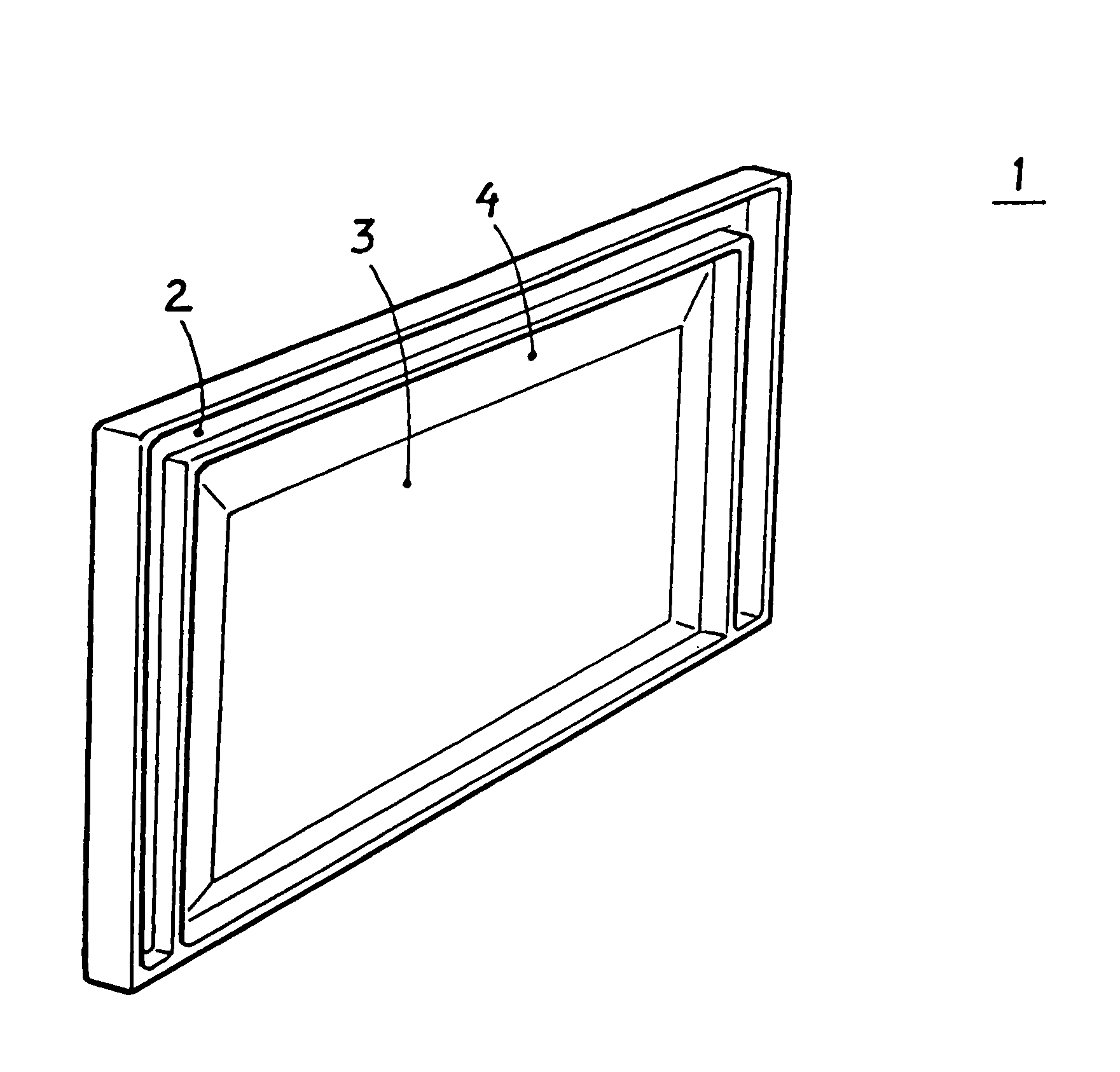
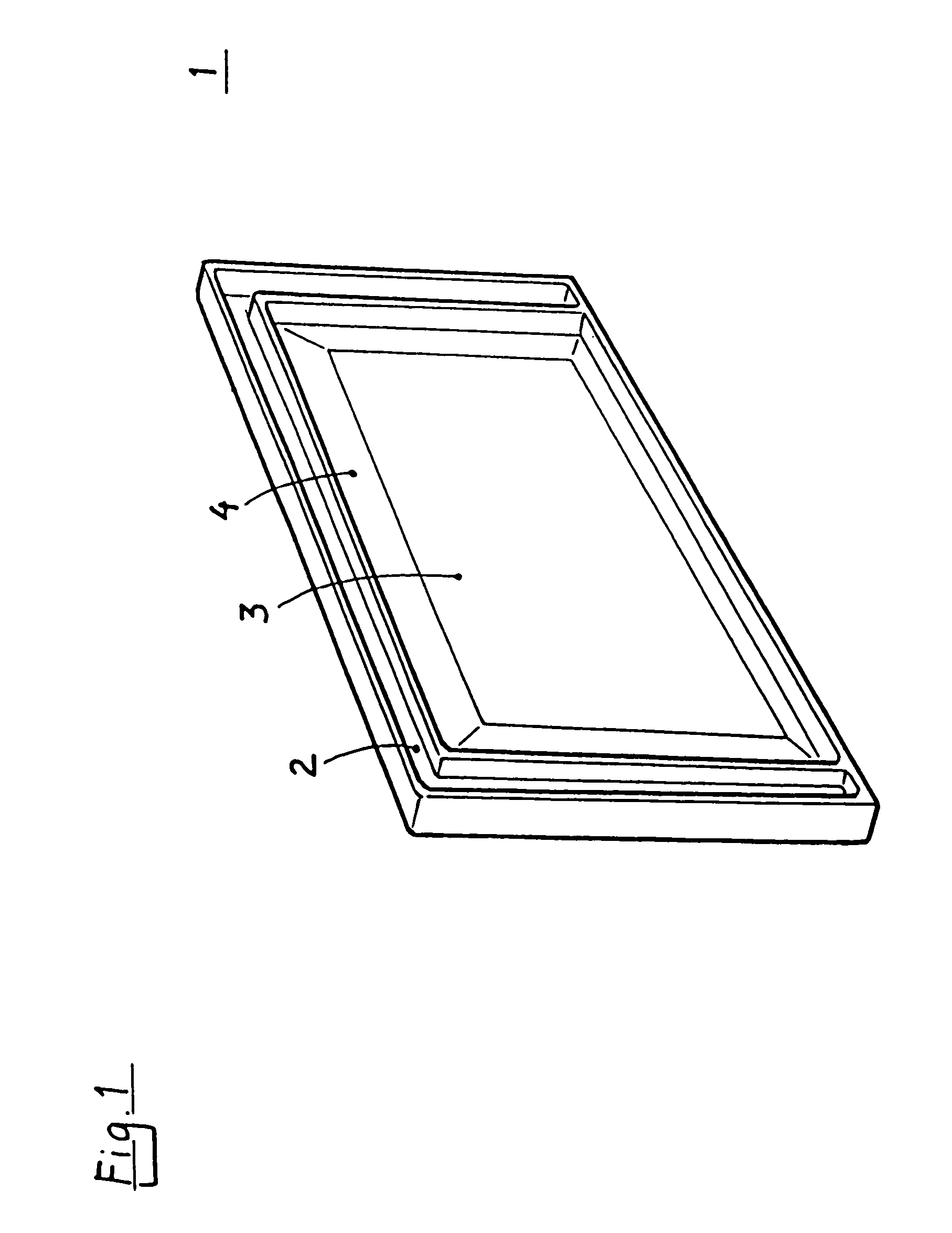
[0013]FIG. 1 shows, in perspective one embodiment of an element 1 with a frame 2 and an intermediate wall section 3. The element 1 includes a carrying structure constituted by the frame 2, and an intermediate wall section 3. The wall section 3 is connected to the frame 2 via a resilient section 4. The resilient section 4 is a part of the wall section 3. Differences in the temperature related shrinkage between the frame 2 and the wall section 3 is absorbed by the resilient section 4 whereby warping of the element 1 is avoided.

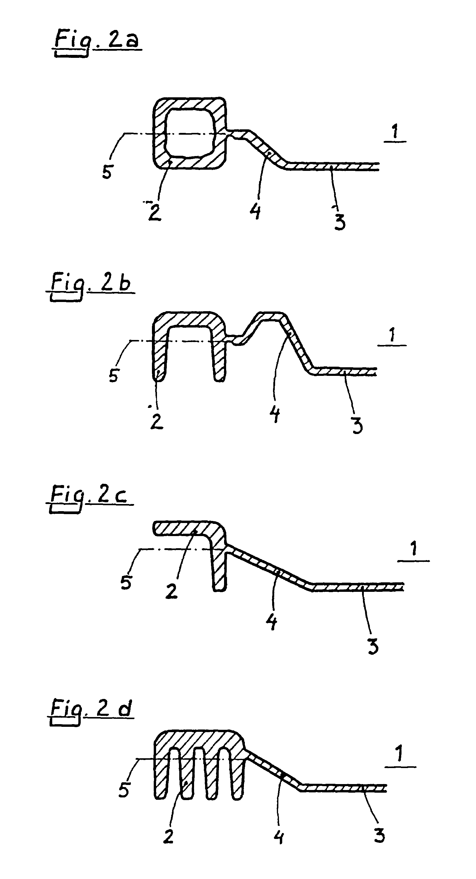
[0014]FIGS. 2a–2d show, in cross-section, parts of different embodiments of an element 1 with profiles constituting a frame 2 of the element 1. The element 1 includes a carrying structure, constituted by the frame 2, and an intermediate wall section 3. The wall section 3 is connected to the frame 2 via a resilient section 4. The resilient section 4 is a part of the wall section 3. The frame 2 is constituted by a U-shaped profile (FIG. 2b), a number of tightly pl...


PUM

PropertyMeasurementUnit
temperatureaaaaaaaaaa
thicknessaaaaaaaaaa
heightaaaaaaaaaa

Abstract

Flat or semi-flat element (1) including a partly or completely circumambient frame (2), which element (1) is manufactured through molding of a polymeric material. The element (1) includes a carrying structure, constituted by the frame (2), and an intermediate wall section (3). The wall section (3) is connected to the frame (2) via a resilient section (4), the resilient section (4) being a part of the wall section (3). The differences in the temperature related shrinkage between the frame (2) and the wall section (3) is absorbed by the resilient section (4), whereby warping of the element (1) is avoided.

Description

BACKGROUND OF THE INVENTION[0001]1. Field of the Invention[0002]The present invention relates to a flat or a semi-flat element including a partly or completely circumambient frame and an intermediate wall section.[0003]2. Description of Related Art[0004]Products made of plastic material are seen almost everywhere today. One way of manufacturing these products is through injection moulding of a thermoplastic material. It is a well known fact that the material thickness in such injection moulded products may not differ too much within the product since problems with warping will otherwise occur. This warping is caused by the temperature related shrinking, which is relatively great in most thermoplastic materials. An injection moulded product will normally be removed from the mould before it is completely cooled since the cycle time is an important economical factor in plastic manufacturing. The remainder of the cooling will hereby take place outside the mould. The shrinkage is related...

Claims


Application Information

Patent Timeline
Patent Type & Authority Patents(United States)
IPC IPC(8): B29D22/00B29D23/00B32B1/08B29C45/00B29C45/17
CPCB29C45/0025B29C45/1704Y10T428/1328Y10T428/1352
Inventor BRAUNER, MANFRED
Owner SCHOELLER ARCA SYST
Why Eureka
Try Eureka