Optoelectronic sensor

a technology of optoelectronic sensors and sensors, applied in the field of optoelectronic sensors, can solve problems such as increasing calcium concentrations, and achieve the effect of preventing device contamination

Inactive Publication Date: 2006-08-15
MASSACHUSETTS INST OF TECH
View PDF11 Cites 15 Cited by
  • Summary
  • Abstract
  • Description
  • Claims
  • Application Information

AI Technical Summary

Benefits of technology

[0009]The device can be contained within a housing made from, for example, aluminum, plastic, or stainless steel. Such a housing can prevent contamination of the device with extraneous organisms. The housing can include two halves attached to each other on one side of the housing by a hinge joint. In applications where an airborne antigen is to be detected, the housing can contain one or more openings for the antigen to pass into the device. Such an opening can be screened by an antigen-permeable barrier such as a metal mesh or a membrane.

Problems solved by technology

Binding of the antigen to the antibodies results in an increase in calcium concentration.

Method used


Image

  • Optoelectronic sensor
  • Optoelectronic sensor
  • Optoelectronic sensor

Examples


example 1

Optoelectronic Device with Housing

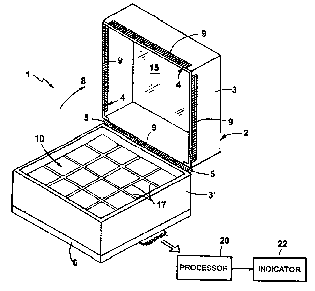
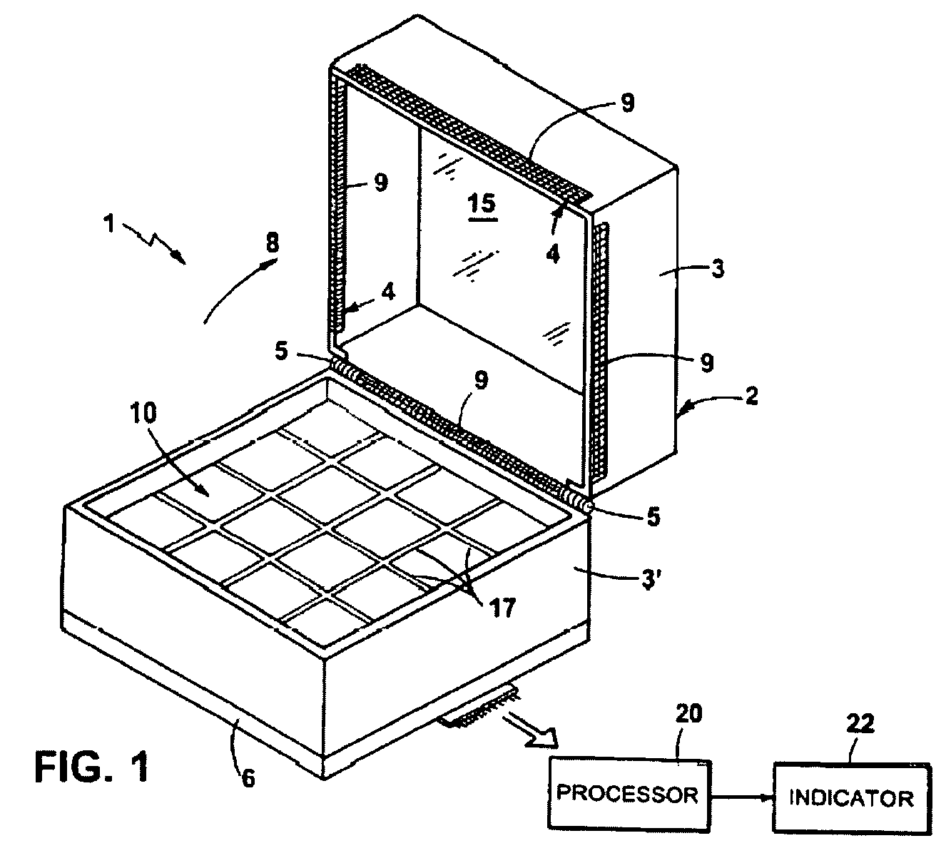
[0037]Referring to FIGS. 1–3, a device 1 for detecting multiple airborne antigens includes a housing 2 having an upper half 3 and a lower half 3′ which together define an inner volume 18 (FIG. 3) of the device. When upper half 3 and lower half 3″ are together (closed position), they also define an opening 4 through which the antigen to be detected enters the device 2. An antigen-permeable mesh 9 is positioned over the opening 4 to prevent the ingress of large particles which could interfere with proper functioning of the inner components. The upper half 3 of the housing 1 is attached to the lower half 3′ by hinge 5, allowing the device 1 to be opened in a direction as indicated by arrow 8. Lower half 3′ has an open bottom to receive an optical detector, here a CCD 6, which is discussed in greater detail below.

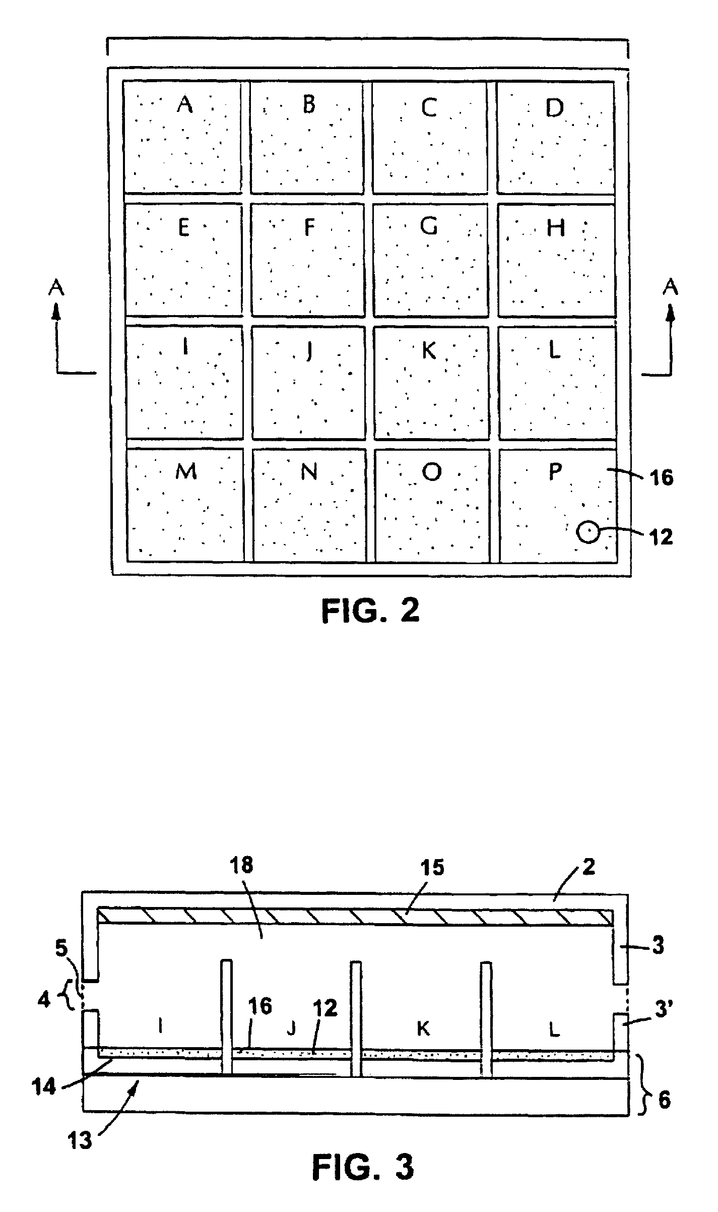
[0038]The top view of the device 1 when the upper half 3 of the housing 2 is removed is shown in FIG. 2. The device 1 includes an array 10 of ...

example 2

Use of B Cells in an Optoelectronic Sensor

[0043]The ability of B cells to emit photons in response to an extracellular signal was evaluated. K46J B cells were loaded with the calcium-sensitive fluorescent dye indo-1, stimulated by contacting the loaded cells with anti-IgM antibodies, and monitored for fluorescence as follows.

[0044]About five million cells were removed from their growth medium and resuspended in 1 ml Hank's Balanced Salt Solution (HBSS). One vial of indo-1 was mixed with 113 μl of fetal bovine serum (FBS) and 25 μl of pluronic F-127 detergent (20% in DMSO). The mixture was incubated at room temperature for five minutes. The FBS was necessary to solubilize the indo-1, even though when the indo-1 was added to the cells, the FBS was capable of temporarily activating the cells.

[0045]After the five minute incubation, 40 μl of 100 mM probenecid was added to the cells to improve loading. Then 15 μl of the indo-1 mixture as prepared above was added. The cells were incubated ...

example 3

Use of Non-B Cells in a Optoelectronic Sensor

[0053]To determine if cell types other than B cells were appropriate for use in an optoelectronic sensor, the murine fibroblast cell line BALB / c 3T3 was evaluated as follows.

[0054]About 7×10⁶ 3T3 cells were removed from a confluent 10 cm2 tissue culture plate by trypsinization. These cells were then treated as describe above for K46J cells, except that 100 μl of fetal bovine serum was used to stimulate calcium mobilization instead of an anti-IgM antibody. Before and after stimulation, the fibroblasts exhibited a fluorescence ratio similar to that seen for K46J cells as discussed above, indicating that fibroblasts, as well as B cells, are suitable for the devices and methods of the invention.

[0055]As a further illustration that fibroblasts can be used in place of B cells in the invention, an in vitro aequorin luminescence assay was performed on aequorin produced in 3T3 cells, and the result compared to that of aequorin produced in K46J cel...


PUM

PropertyMeasurementUnit
temperatureaaaaaaaaaa
pHaaaaaaaaaa
concentrationaaaaaaaaaa

Abstract

A device for detecting the presence of an antigen including (1) a cell having antibodies which are expressed on the surface of the cell and are specific for the antigen to be detected, where binding of the antigen to the antibodies results in an increase in calcium concentration in the cytosol of the cell, the cell further having a emitter molecule which, in response to the increased calcium concentration in the cytosol, emits a photon; (2) a liquid medium for receiving the antigen and in which the cell is immersed; and (3) an optical detector arranged for receiving the photon emitted from the cell.

Description

RELATED APPLICATIONS[0001]This application is a continuation of U.S. application Ser. No. 09 / 848,811 filed May 4, 2001 now U.S. Pat. No. 6,800,448, which is a continuation of Ser. No. 09 / 169,196 filed Oct. 9, 1998, now U.S. Pat. No. 6,248,542, which is a continuation-in-part of U.S. application Ser. No. 08 / 987,410 filed Dec. 9, 1997, now U.S. Pat. No. 6,087,114. The entire teachings of the above applications are incorporated herein by reference.GOVERNMENT SUPPORT[0002]The invention was supported, in whole or in part, by Contract Number F19628-95-C-0002 awarded by the U.S. Air Force. The government has certain rights in the invention.BACKGROUND OF THE INVENTION[0003]The need for small, fast, and sensitive detectors of biological agents which are able to continuously monitor an environment for extended periods of time is underscored by the proliferation of biological and chemical weapons, the poor man's nuclear weapon. Under battlefield conditions, a useful detector would rapidly aler...

Claims


Application Information

Patent Timeline
Patent Type & Authority Patents(United States)
IPC IPC(8): G01N33/53G01N21/76G01N33/569G01N33/58
CPCG01N21/6454G01N21/76G01N21/77G01N33/54366G01N33/554G01N33/582G01N33/56972Y10S436/805G01N2021/6482G01N2021/7786Y10S435/808
Inventor RIDER, TODD H.BORTOLIN, LAURA
Owner MASSACHUSETTS INST OF TECH
Why Eureka
Try Eureka