Image sensor with a voltage maintaining capacitor and an ac-signal blocking resistor, and imaging system comprising the image sensor

a voltage maintaining capacitor and resistor technology, applied in the field of image sensor with voltage maintaining capacitor and acsignal blocking resistor, and imaging system comprising image sensor, can solve the problems of cost, size, weight, and complexity of the configuration of the image sensor itsel

Inactive Publication Date: 2006-08-15
HAMAMATSU PHOTONICS KK
View PDF8 Cites 17 Cited by
  • Summary
  • Abstract
  • Description
  • Claims
  • Application Information

AI Technical Summary

Benefits of technology

[0007]The present invention has been accomplished in order to solve the above problem and an object of the present invention is to provide an image sensor constructed in an inexpensive and simple configuration without need for use of the cable connecting the image sensor to the main body part, and an imaging system using the image sensor.
[0011]Accordingly, the image sensor alone can perform the image pickup operation, without need for the battery and the radio system, so that the image sensor can be obtained in the inexpensive and simple configuration without need for the cable for connection to the main body part.

Problems solved by technology

However, while the techniques disclosed in these Applications can obviate the need for the cable connecting the image sensor to the main body part, they are disadvantageous in terms of cost, size, and weight because of the inclusion of the battery and radio system in the image sensor, and also involve a problem that the configuration of the image sensor itself becomes complicated.

Method used


Image

  • Image sensor with a voltage maintaining capacitor and an ac-signal blocking resistor, and imaging system comprising the image sensor
  • Image sensor with a voltage maintaining capacitor and an ac-signal blocking resistor, and imaging system comprising the image sensor
  • Image sensor with a voltage maintaining capacitor and an ac-signal blocking resistor, and imaging system comprising the image sensor

Examples


Embodiment Construction

[0019]Embodiments of the present invention will be described below in detail with reference to the accompanying drawings. The same elements will be denoted by the same reference symbols throughout the description of the drawings, without redundant description thereof.

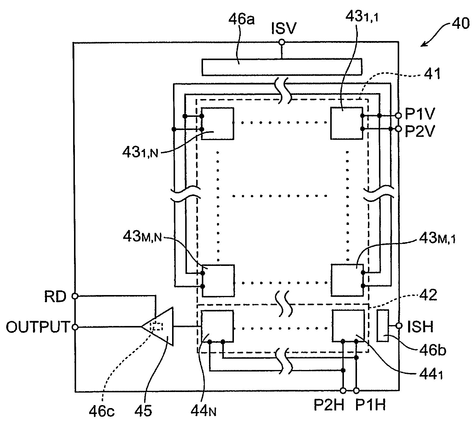
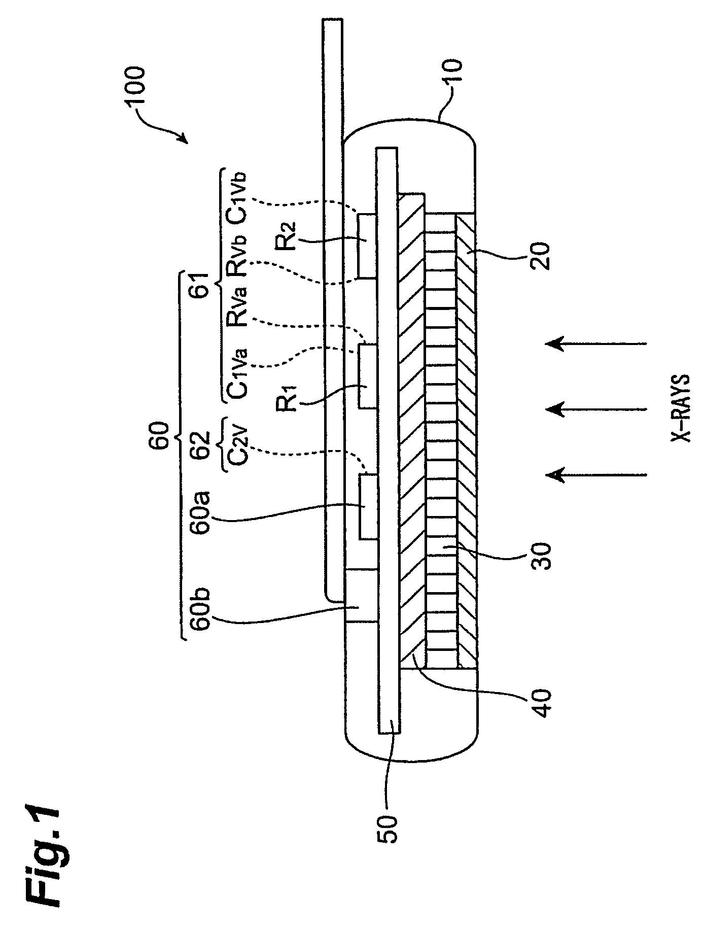
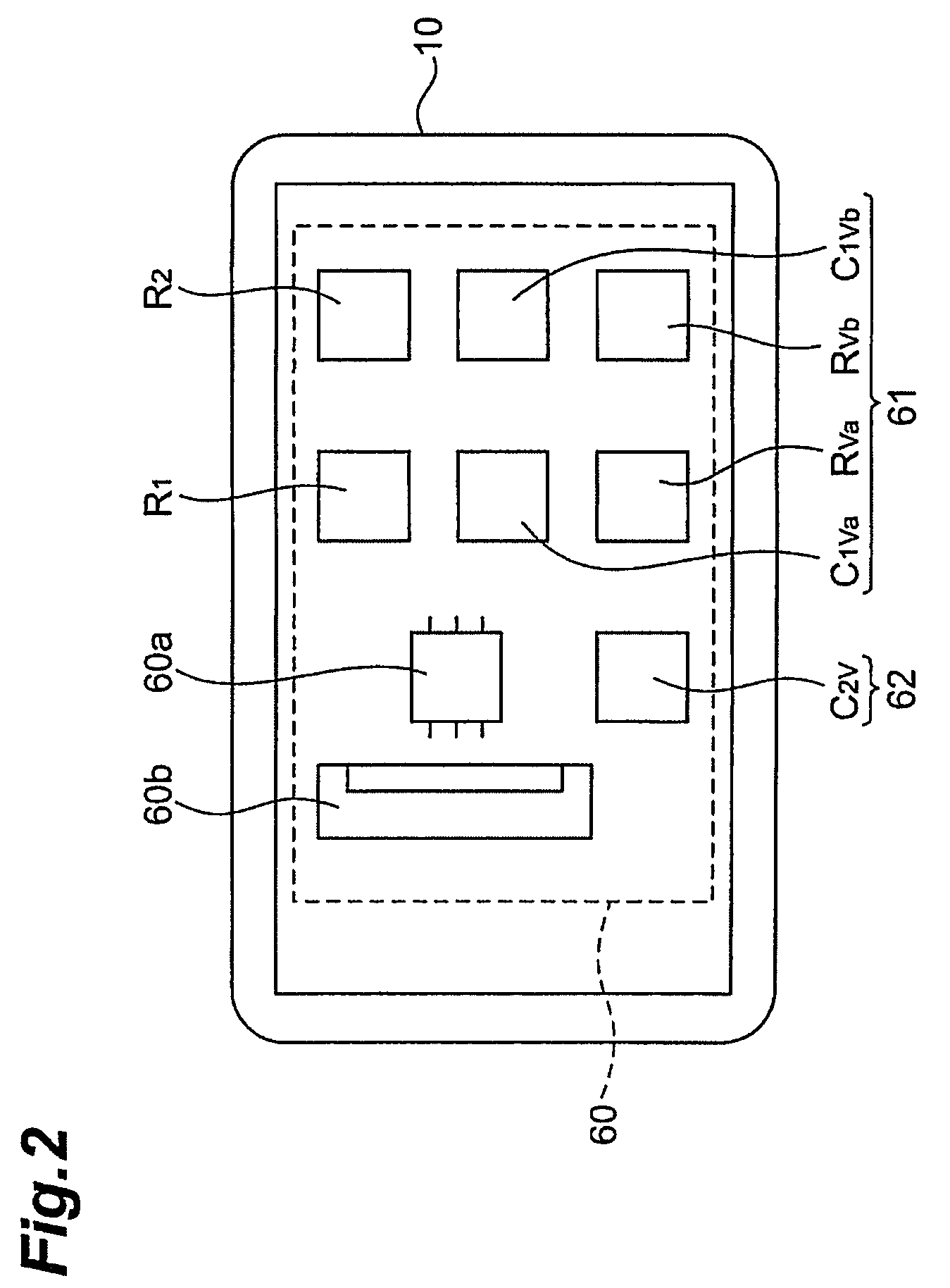
[0020]First, an embodiment of the image sensor according to the present invention will be described. FIG. 1 is a sectional view to illustrate the configuration of image sensor 100 according to the present embodiment. The image sensor 100 has casing 10, scintillator 20, fiber optical plate (FOP) 30, CCD image pickup device 40, ceramic substrate 50, and external component group 60. The casing 10 covers the scintillator 20, FOP 30, CCD image pickup device 40, ceramic substrate 50, and external component group 60.

[0021]The scintillator 20 converts X-rays incident through the casing 10, into visible light. The FOP 30 guides the visible light as converted by the scintillator 20, to the CCD image pickup device 40. The CCD imag...


PUM


Abstract

An image sensor 100 is provided with a first voltage maintainer 61 including two first voltage maintaining capacitors C1Va, C1Vb for maintaining a voltage of signal input electrode 47, and a second voltage maintainer 62 including a second voltage maintaining capacitor C2V for maintaining a voltage of bias voltage input electrode 46. This image sensor 100, even in a disconnected state from main body part 200, is able to maintain the voltage of bias voltage input electrode 46 and the voltage of signal input electrode 47 during an image pickup operation and thus to implement image pickup.

Description

TECHNICAL FIELD[0001]The present invention relates to an image sensor including an array of pixels to generate their respective charges in response to incidence of light, and an imaging system using the image sensor.BACKGROUND ART[0002]An image sensor includes an array of pixels to generate their respective charges in response to incidence of light and is configured to output electric signals according to amounts of the charges generated in the respective pixels.[0003]An intraoral sensor is one of such image sensors. This intraoral sensor is configured to transmit the electric signals according to amounts of charges through a cable (about two to three meters) to the main body part. The main body part connected to the intraoral sensor operates to display an image generated on the basis of the transmitted electric signals, on a display device or print the image by a printer. The cable connecting the intraoral sensor to the main body part is also used to feed clock signals to order tra...

Claims


Application Information

Patent Timeline
Patent Type & Authority Patents(United States)
IPC IPC(8): H01L27/00G01T1/20H01L27/146H04N1/028H04N1/04H04N5/225H04N5/32H04N5/335H04N5/361H04N5/369
CPCA61B6/4233H01L27/146H04N5/32H04N5/2251H04N5/23241H04N3/1512H01L27/14806H04N25/76
Inventor MIYAGUCHI, KAZUHISA
Owner HAMAMATSU PHOTONICS KK
Why Eureka
Try Eureka