
Switching power supply utilizing oscillator frequency tuner for load driving capability under peak load condition

a technology of oscillator frequency tuner and switching power supply, which is applied in the direction of electric variable regulation, process and machine control, instruments, etc., can solve the problems of incompetence of conventional switching power supply to drive load, general insufficient load driving capability, etc., and achieve the effect of improving load driving capability

Inactive Publication Date: 2006-08-15
DELTA ELECTRONICS INC +1
View PDF2 Cites 3 Cited by
  • Summary
  • Abstract
  • Description
  • Claims
  • Application Information

AI Technical Summary

Benefits of technology

[0005]A first object of the present invention is to provide a switching power supply capable of providing an improved load driving capability under peak load condition.
[0006]A second object of the present invention is to provide an oscillator frequency tuner that can enhance the load driving capability of a switching power supply under peak load condition.
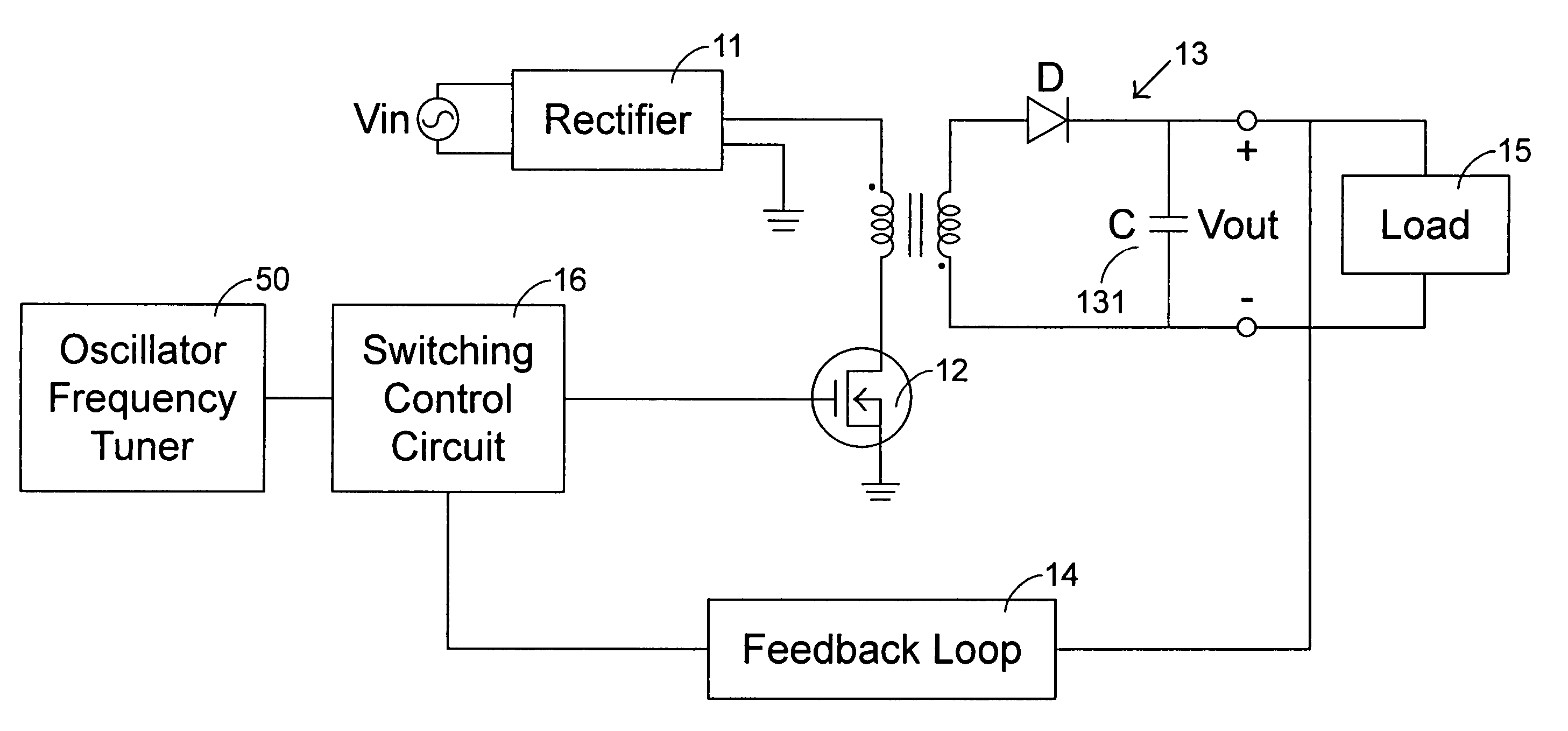
[0007]To this end, a switching mode power supply is provided and includes a rectifier which receives an input voltage and converts the input voltage into a rectified DC voltage, a switch device connected to the rectifier, a transformer connected to the switch device for transducing the rectified DC voltage into a magnetization energy by a primary winding and transferring the magnetization energy across a secondary winding according to on / off operations of the switch device, a switching control circuit which generates a switching control signal to regulate a duty cycle of the switch device, and an oscillator frequency tuner that modulates an oscillator frequency of the switching control circuit according to a feedback control signal provided by the switching control circuit to broaden a maximum duty cycle of the switching control circuit when the switching power supply is operating under peak load condition.

Problems solved by technology

Generally, the maximum output power of a switching power supply is restrained by the limited pulse width of the PWM signal and thus its load driving capability is generally insufficient.
Under this condition, a conventional switching power supply is incompetent to drive the load because the load power has exceeded its maximum load driving capability.

Method used


Image

  • Switching power supply utilizing oscillator frequency tuner for load driving capability under peak load condition
  • Switching power supply utilizing oscillator frequency tuner for load driving capability under peak load condition
  • Switching power supply utilizing oscillator frequency tuner for load driving capability under peak load condition

Examples


Embodiment Construction

[0016]An exemplary embodiment embodying the features and advantages of the present invention will be expounded in following paragraphs of descriptions. It is to be realized that the present invention is allowed to have various modification in different respects, all of which are without departing from the scope of the present invention, and the description herein and the drawings are intended to be taken as illustrative in nature, and are not limitative.

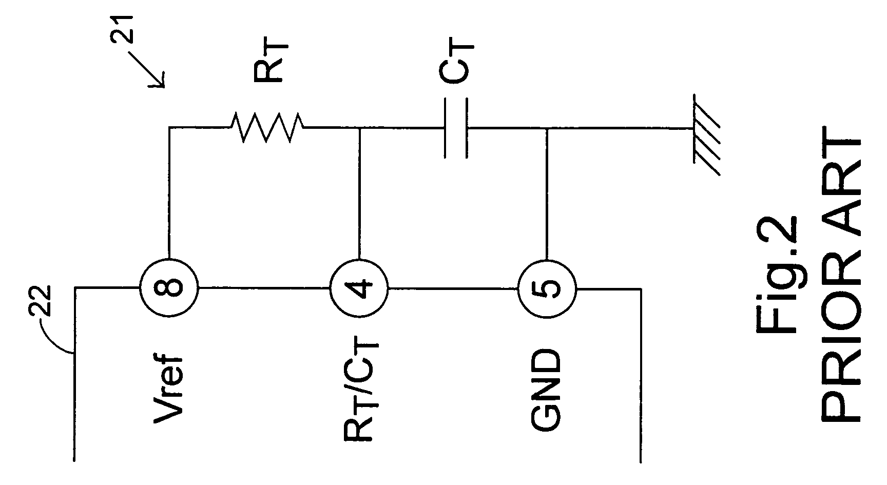
[0017]Referring to FIG. 2, a prior art UC3843 current-mode PWM controller 22 is partially shown in combination of a control circuitry 21. In the exemplary embodiment, the UC3843 PWM controller 22 is to be taken as a standard exemplification as the switching control circuit 16 for use in a switching power supply. In FIG. 2, a resistor RT and an oscillating timing capacitor CT form a control circuitry 21 for the PWM controller 22 that are respectively connected between the eighth pin and the fourth pin of the PWM controller 22 and betw...


PUM


Abstract

A switching power supply including an oscillator frequency tuner to enhance its load driving capability is presented. The oscillator frequency tuner includes a plurality of capacitors connected between a reference voltage output of the switching control circuit and a ground terminal, at least one bypass switch coupled across at least one of the capacitors for controlling the charging and discharging operation of the capacitor coupled therewith, and a bypass switch controller for controlling a switching state of the bypass switch. When the switching power supply is operating under a peak load condition, the bypass switch controller receives a feedback control signal and instructs the bypass switch to bypass current, and thus reducing the equivalent timing capacitance of the switching control circuit for increasing the maximum duty cycle of the switching control circuit.

Description

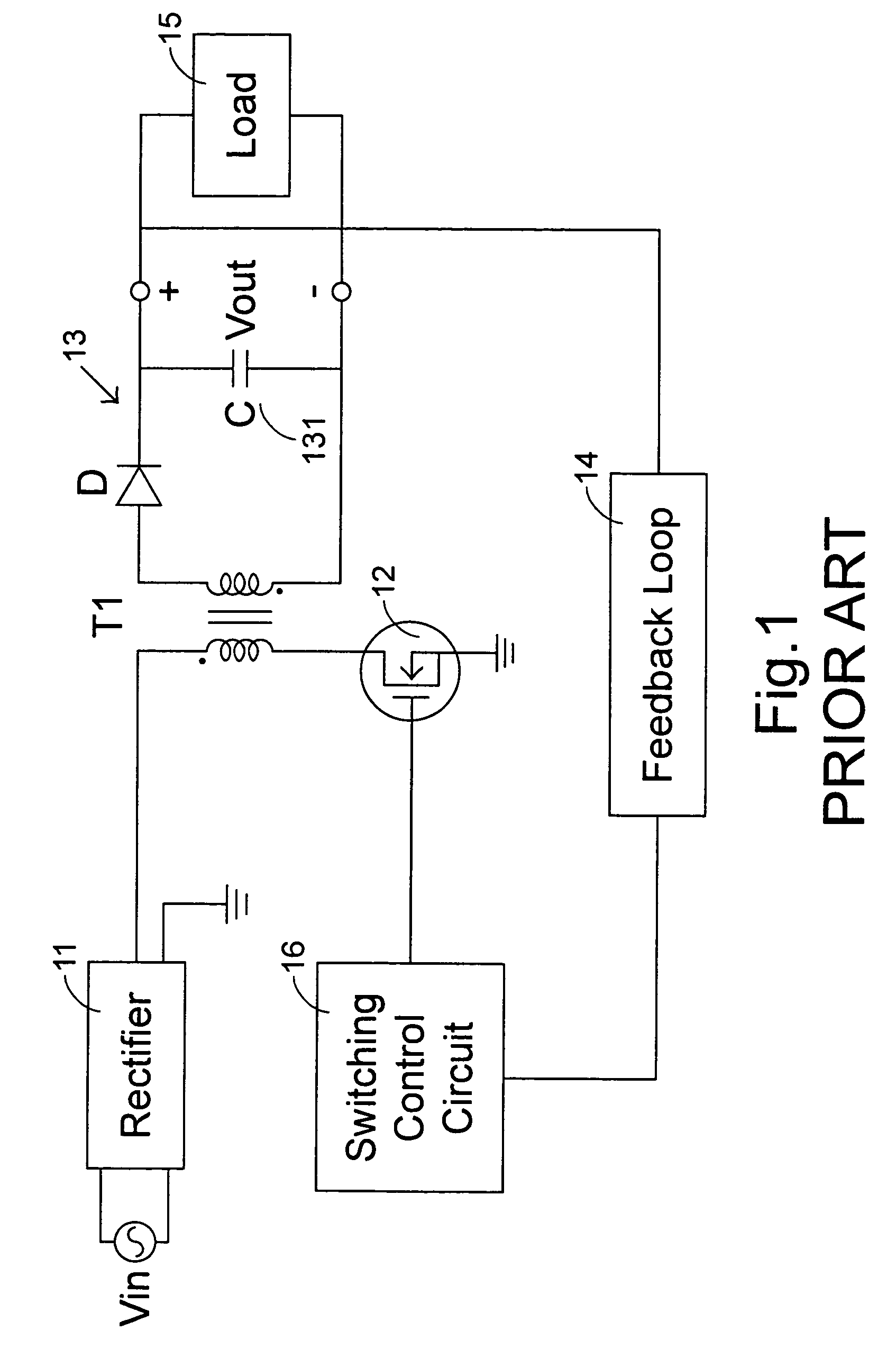
FIELD OF THE INVENTION[0001]The present invention is related to a switching power supply, and more particularly to a switching power supply that utilizes an oscillator frequency tuner capable of dynamically adapting the oscillator frequency and the maximum duty cycle of a switching control circuit of the switching power supply, and further enhancing the load driving capability of the switching power supply under a peak load condition.BACKGROUND OF THE INVENTION[0002]A typical representation of a switching power supply is depicted in FIG. 1. In the switching power supply of FIG. 1, a rectifier 11 is used to receive an input AC voltage Vin and convert the input AC voltage Vin into a rectified DC voltage. A switch device 12 is coupled between an output end of the rectifier 11 and the primary winding of a transformer T1. The transformer T1 is provided to receive the rectified DC voltage from its primary winding and acts as an energy storage device to store magnetization energy therein w...

Claims


Application Information

Patent Timeline
Patent Type & Authority Patents(United States)
IPC IPC(8): H02M3/335H02M3/24
CPCH02M3/33507H02M2001/0025H02M2001/0019H02M1/0019H02M1/0025
Inventor ALLWYN, JACOB D'CUNHARUPESH, KUMAR TANDONSUPAPORN, ITTASAKULTASI, KUEI HSIANG
Owner DELTA ELECTRONICS INC
Learn More