
Ergonomic hand tool

a hand tool and ergonomic technology, applied in the field of hand tools, can solve the problems of early fatigue, soreness, medical problems, and the medical problems associated with operating hand tools are substantially diminished, and achieve the effect of efficient storage and marketing and efficient shipping of products

Inactive Publication Date: 2006-08-22
LEGACY HLDG
View PDF20 Cites 10 Cited by
  • Summary
  • Abstract
  • Description
  • Claims
  • Application Information

AI Technical Summary

Benefits of technology

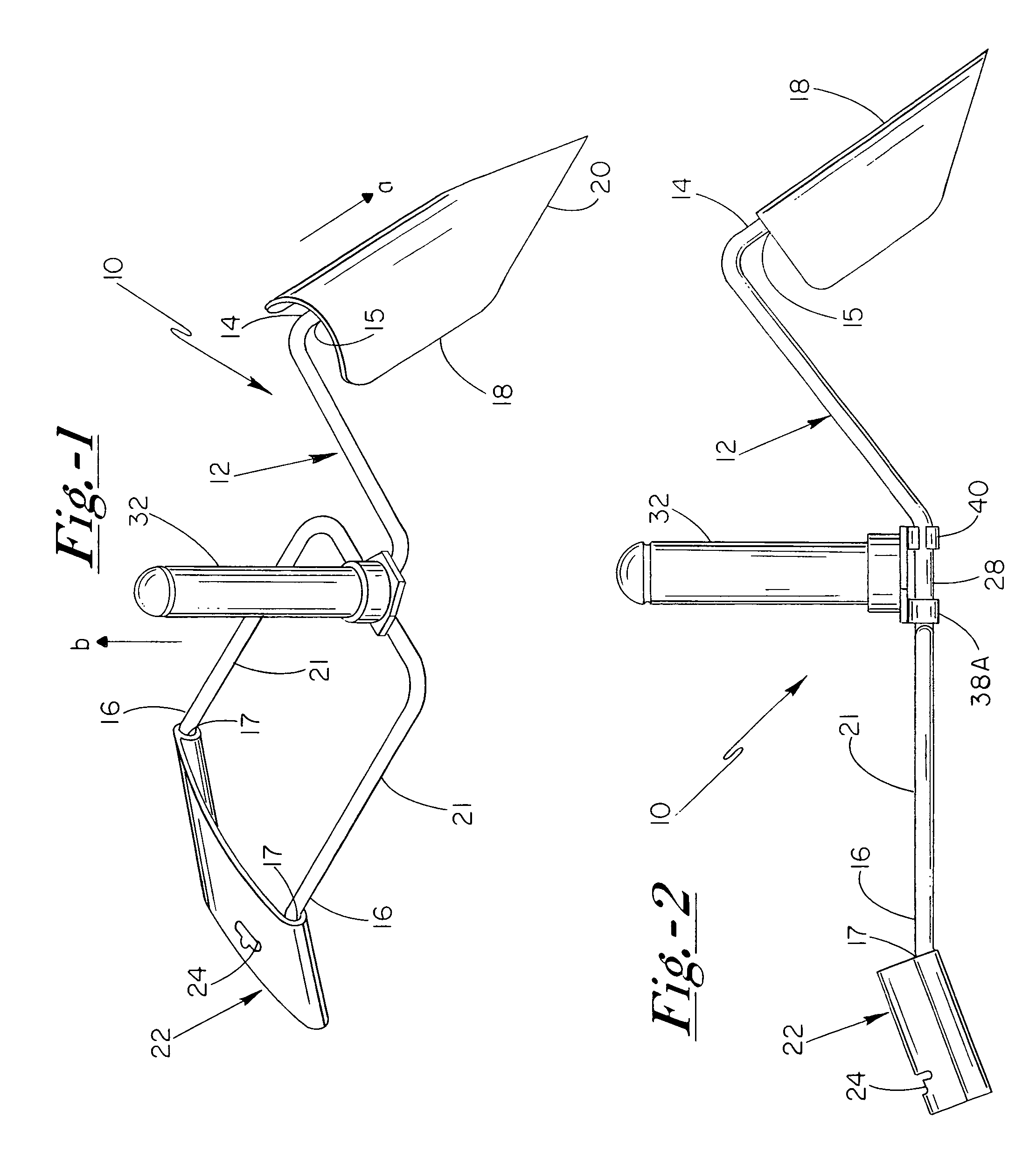
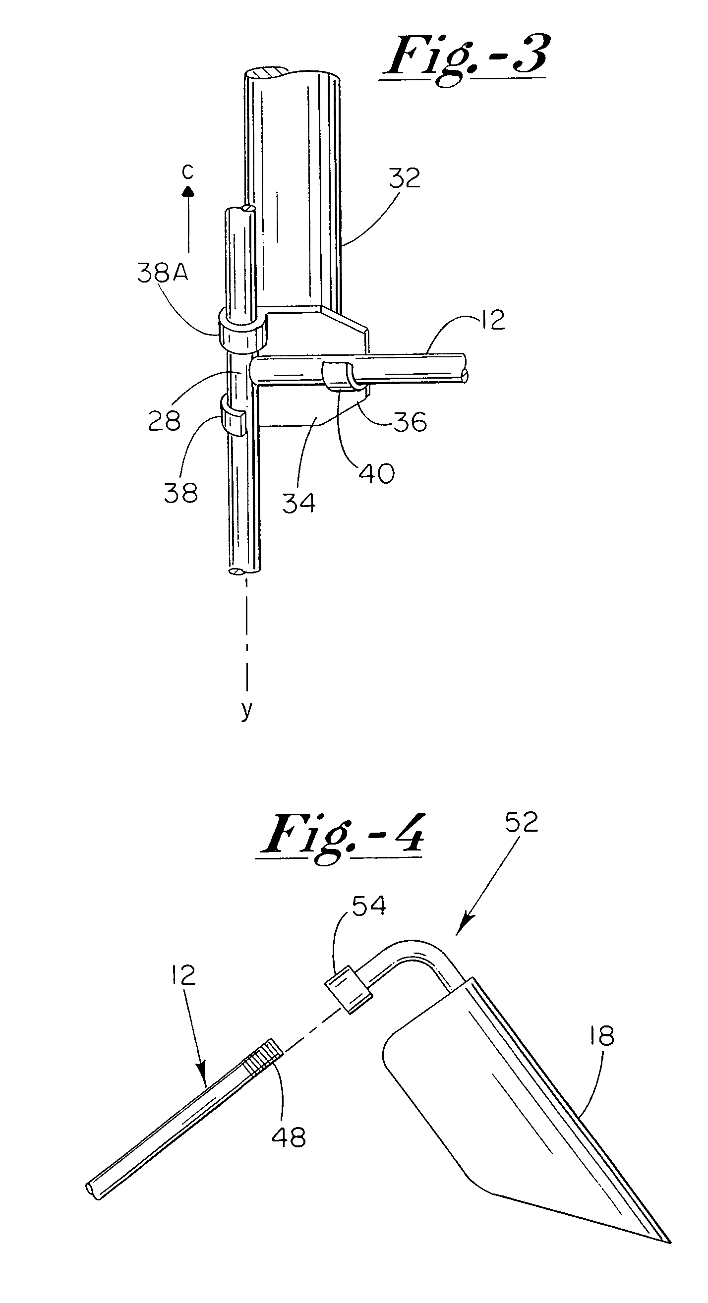
[0009]By means of the present invention, an ergonomic hand tool is provided which incorporates a frame having a working element on a first end thereof, a brace disposed at a second opposed end thereof, and a handle disposed at a portion of the frame intermediate the working element and the brace. The handle is preferably pivotally secured to the tool frame so as to have the capability of pivoting into an orientation substantially parallel to the tool frame. Such a pivoting characteristic of the handle provides for more efficient storage and marketing of the hand tool on retail store shelves, as well as for more efficient shipping of the product in a nested configuration.

Problems solved by technology

The application of such forces at the user's wrist can result in early fatigue, soreness, and even medical problems, such as carpal tunnel syndrome.
As a result, fatigue, soreness, and medical problems associated with operating hand tools is substantially diminished.
While the devices described in the above-cited patents provide useful operational characteristics, the fixed nature of the intermediate handle of such devices renders the tools somewhat difficult to store, display, and ship.
In addition, the fixed handle configurations described in the cited patents do not provide for a convenient means of replacing the handle with a customized and / or replacement handle.

Method used


Image

  • Ergonomic hand tool
  • Ergonomic hand tool
  • Ergonomic hand tool

Examples


Embodiment Construction

[0020]The objects and advantages enumerated above together with other objects, features, and advances represented by the present invention will now be presented in terms of detailed embodiments described with reference to the attached drawing figures which are intended to be representative of various possible configurations of the invention. Other embodiments and aspects of the invention are recognized as being within the grasp of those having ordinary skill in the art.

[0021]With reference to the enclosed drawing figures, and first to FIG. 1, a hand tool 10 of the present invention is illustrated incorporating a frame 12 having a distal portion 14 and a proximal portion 16. Hand tool 10 further includes a working element 18 that is operably coupled to distal end 15 of distal portion 14. Working element 18 preferably includes a working portion 20 that is oriented along a first direction “a” with respect to frame 12.

[0022]Working element 18 is illustrated in FIG. 1 as being a shovel o...


PUM


Abstract

An ergonomic hand tool for enhancing the leverage available to a user includes a frame having a distal portion and a proximal portion, and a working element operably coupled to a distal end of the distal portion. The frame further includes a handle that is pivotally coupled to the frame at a portion thereof intermediate the proximal portion and the distal portion. A brace structure is preferably operably coupled to the proximal portion of the frame, with the brace structure being configured to operably brace against an upper side of a user's forearm while the user operably grasps the handle.

Description

CROSS-REFERENCE TO RELATED APPLICATIONS[0001]This application is a continuation-in-part of co-pending U.S. patent application Ser. No. 10 / 786,767, filed on Feb. 25, 2004, and entitled “ERGONOMIC HAND TOOL”, the content of which is incorporated herein in its entirety.FIELD OF THE INVENTION[0002]The present invention relates to hand tools generally, a more particularly to a hand tool having an ergonomic design that increases the fulcrum length achieved when utilized by a user in comparison to conventional hand tools. The ergonomic hand tool of the present invention correspondingly minimizes stress placed upon the user's wrist during operation of the tool.BACKGROUND OF THE INVENTION[0003]Hand tools, such as those commonly utilized in garden or yard applications, have been embodied in a wide variety of configurations. Typically, however, such hand tools comprise a frame having a working element disposed at one end of the frame and a handle disposed at the opposite end of the frame. Thro...

Claims


Application Information

Patent Timeline
Patent Type & Authority Patents(United States)
IPC IPC(8): A01B1/00B26B15/00
CPCA01B1/06B25G1/102B25G3/36Y10T403/7194Y10T403/7073Y10T403/7123
Inventor HURT, DANIEL P.
Owner LEGACY HLDG
Learn More