Airbag, airbag device and vehicle

a technology for airbags and vehicles, applied in the field of airbags, can solve the problems of insufficient airbags, achieve the effects of reducing the number of inflators, reducing the load on the breastbone, and reducing manufacturing costs

Active Publication Date: 2006-08-22
JOYSON SAFETY SYST JAPAN GK
View PDF22 Cites 11 Cited by
  • Summary
  • Abstract
  • Description
  • Claims
  • Application Information

AI Technical Summary

Benefits of technology

[0021]In the present invention, the distance between the distal ends of the left half and right half airbags is set to be 150 to 450 mm when the airbag is inflated. As a result, the left half airbag faces a center of the left side of the thorax and the inflated right half airbag faces a center of the right side of the thorax, thereby securely receiving the occupant's upper body around the rib bones. Also, the distance from the distal ends to the deepest bottom of the space is set to be 280 to 480 mm, thereby decreasing a load on the breastbone.
[0022]In the present invention, a common inflator may be provided for inflating both the left half airbag and the right half airbag, thereby reducing the number of the inflators and a manufacturing cost.
[0023]In the present invention, the left half airbag is connected with the right half airbag at the middle portions of the surfaces facing each other in a direction that the airbag deploys. When the airbag is inflated, a distance from the distal ends of the left and right half airbags to the connected middle portions may be 50 to 300 mm. With such a configuration, when one of the half airbags inflates later, the other of the half airbags facilitates the one of the half airbags to be inflated by pulling the one of the half airbags. Also, the one of the half airbags starts to pull the other of the half airbags in the direction of deployment at an early stage when the one of the half bags is inflated up to the middle. Accordingly, both of the left and right half airbags are inflated smoothly and substantially uniformly toward left and right sides from the early stage of the inflation. Further, the connected portions are located at a deep position in the space between the left and right half airbags, so that the joined portions do not apply a load on the breastbone.
[0024]In the present invention, the left and right half airbags are formed of a plurality of the joined panels. The panels are joined at the joined portions at an outside and the middle of the airbag in the direction of deployment. The joined portions at the middle of the opposing surfaces of the left and right half airbags may be connected. In this case, a tie panel for connecting the left half airbag and the right half airbag is not necessary, thereby reducing a cost of the airbag.
[0025]In the present invention, the vent holes are provided for discharging gas therethrough upon receiving the occupant, thereby absorbing the impact on the occupant. The vent holes are formed in the outer side surfaces at the upper front areas from the middle portions of the side surfaces. When the airbag is inflated, the horizontal distance L1 between the rear edge of the instrumental panel and the distal end of the airbag and the horizontal distance L2 between the rear edge of the instrument panel and the vent hole has a ratio (L2 / L1) of 0.25 to 0.5. Also, when the airbag is inflated, the vertical distance H1 between an upper edge of the instrumental panel and the upper edge of the airbag and the vertical distance H2 between the upper edge and the vent hole has a ratio (H2 / H1) of 0.3 to 0.5. When the vent holes are located at the relatively upper front areas, it is possible to securely prevent the discharged gas through the vent holes from affecting the occupant. Further, when the ratio (L2 / L1) is 0.25 to 0.5 and the ratio (H2 / H1) is 0.3 to 0.5, the vent holes do not closely contact an interior of the vehicle such as a door glass or A pillar, so that the gas is smoothly discharged through the vent holes.
[0026]In the present invention, it is possible to protect the occupant even when the airbag is inflated with a relatively low gas pressure. When the airbag is inflated with the maximum pressure less than, for example, 440 kPa, it is still possible to protect the occupant. The vehicle provided with the airbag may be further provided with a curtain airbag device, a knee airbag device, a knee protector or a seat cushion bag device to protect the occupant.

Problems solved by technology

Therefore, the one of the half airbags does not sufficiently pull the other of the half airbags through the tie panel until the one of the half airbags is inflated up to the distal end.

Method used


Image

  • Airbag, airbag device and vehicle
  • Airbag, airbag device and vehicle
  • Airbag, airbag device and vehicle

Examples


Embodiment Construction

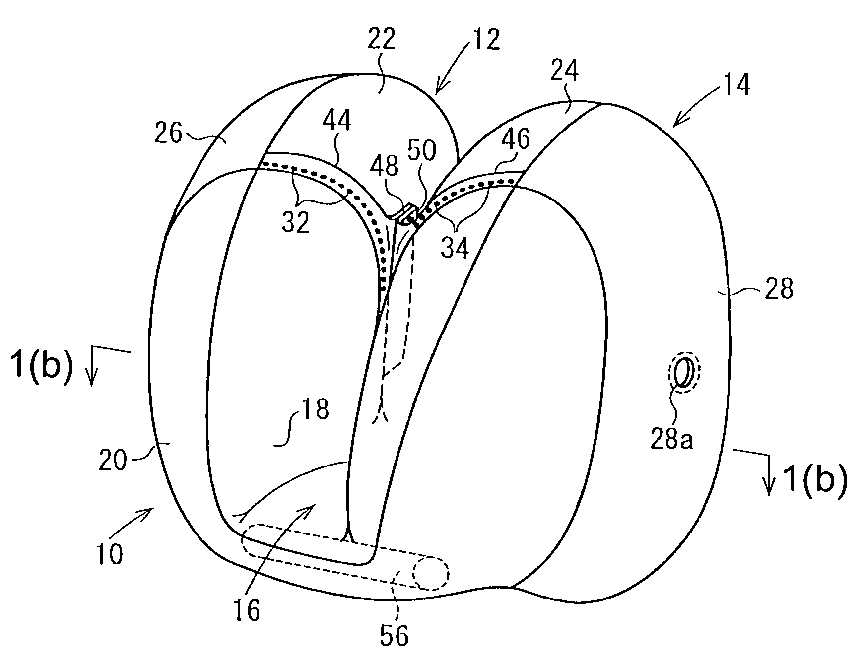
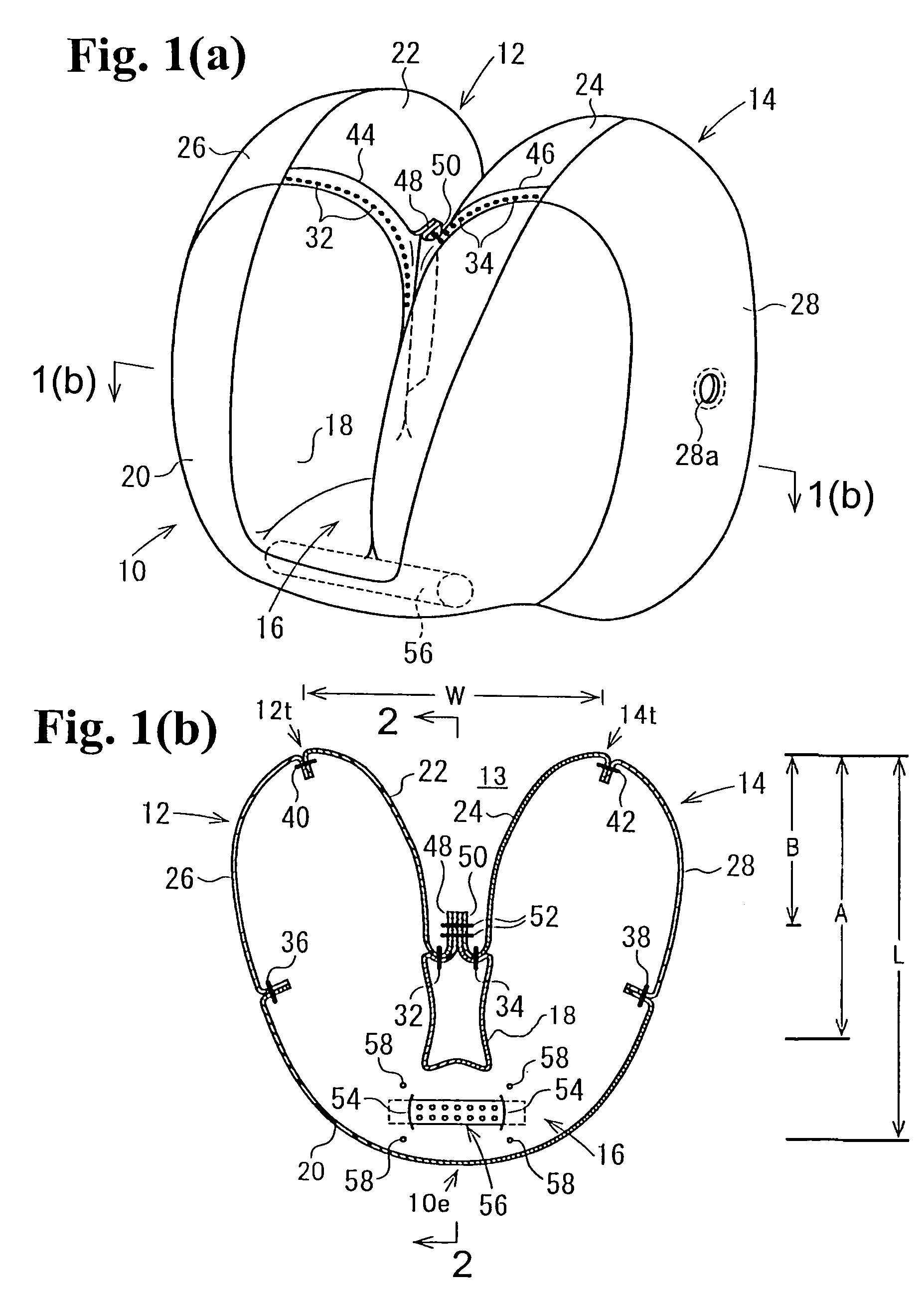
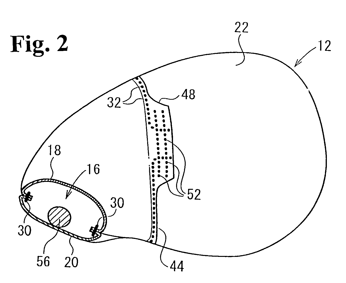
[0034]Hereunder, embodiments of the present invention will be described with reference to the accompanying drawings. FIG. 1(a) is a perspective view of an inflated airbag according to an embodiment of the present invention, and FIG. 1(b) is a sectional view taken along line 1(b)—1(b) in FIG. 1(a). FIG. 2 is a sectional view taken along line 2—2 in FIG. 1(b). FIG. 3(a) is an exploded perspective view of the airbag, and FIG. 3(b) is an enlarged view of a portion 3(b) in FIG. 3(a).

[0035]An airbag 10 includes a right half airbag 12 to be inflated at a front right of a vehicle occupant, a left half airbag 14 to be inflated at a front left of the occupant, and a communicating portion 16 for communicating an end of the right half airbag 12 with an end of the left half airbag 14. The communicating portion 16 is located at a side of a base of the airbag 10. Accordingly, the right half airbag 12 and the left half airbag 14 are inflated toward a direction that the half airbags move away from t...


PUM


Abstract

An airbag device includes an airbag and an inflator disposed at a side of a base portion of the airbag for inflating the airbag. The airbag includes a left half airbag with a vent hole to be inflated at a front left of a vehicle occupant, and a right half airbag with a vent hole to be inflated at a front right of the vehicle occupant. The distal ends of the left half airbag and the right half airbag are spaced part from each other to form an empty space therebetween facing the vehicle occupant when the airbag is inflated.

Description

CROSS REFERENCE TO RELATED APPLICATION[0001]This is a continuation-in-part application of patent application Ser. No. 10 / 671,801 filed on Sep. 29, 2003.BACKGROUND OF THE INVENTION AND RELATED ART STATEMENT[0002]The present invention relates to an airbag for protecting a vehicle occupant in the event of vehicle collision, and specifically relates to an airbag having a left half airbag to be inflated at a front left of the occupant, and a right half airbag to be inflated at a front right of the occupant. The present invention also relates to an airbag device provided with the airbag and a vehicle provided with the airbag device.[0003]Japanese Patent Publication (KOKAI) No. 04-292239 has disclosed an airbag for protecting a vehicle occupant in the event of vehicle collision. The airbag has a left half airbag to be inflated at a front left of the occupant, and a right half airbag to be inflated at the front right of the occupant. A common inflator inflates both the left half and right h...

Claims


Application Information

Patent Timeline
Patent Type & Authority Patents(United States)
IPC IPC(8): B60R21/16B60R21/00B60R21/233
CPCB60R21/233B60R21/2338B60R2021/23386B60R2021/0004B60R2021/0044B60R21/239
Inventor HASEBE, MASAHIRONARIMOTO, YUKITOSHI
Owner JOYSON SAFETY SYST JAPAN GK
Why Eureka
Try Eureka