Powerfold exterior mirror assembly

a technology for exterior mirrors and assemblies, applied in the direction of mirrors, mountings, instruments, etc., can solve the problems of head portion vibrating relative to the base portion, and achieve the effects of enhancing the vibrational performance of the exterior rearview mirror assembly, limiting or substantially reducing the vibration of the movable mirror portion, and enhancing the vibrational performan

Inactive Publication Date: 2006-08-22
DONNELLY CORP
View PDF23 Cites 45 Cited by
  • Summary
  • Abstract
  • Description
  • Claims
  • Application Information

AI Technical Summary

Benefits of technology

[0004]The present invention provides a powerfold exterior rearview mirror assembly which provides enhanced vibrational performance. The exterior rearview mirror assembly includes a movable portion or head portion and a base portion mountable at an exterior portion of a vehicle. The mirror assembly includes a motor or motorized actuator that is operable to pivot the movable portion relative to the base portion. The powerfold exterior rearview mirror assembly of the present invention includes a resilient element or member positioned between the actuator and the actuator cavity, which is the receiving portion of the movable mirror portion. The resilient element may function to provide a secure attachment of the movable mirror portion relative to the actuator and base portion and may limit or substantially reduce vibration of the movable mirror portion to enhance the vibrational performance of the exterior rearview mirror assembly.
[0005]According to an aspect of the present invention, an exterior rearview mirror assembly for a vehicle includes a base portion mounted to the vehicle and a movable portion that is pivotable relative to the base portion via a motor or motorized actuator or powerfold unit or the like. The powerfold unit is operable to pivot the movable portion relative to the base portion. The powerfold unit is mounted at one of the movable portion and the base portion and engages a receiving portion of the other of the movable portion and the base portion. A resilient element is positioned between and at least partially in engagement with the powerfold unit and the receiving portion. The resilient element is resilient and may at least partially compress as the powerfold unit is engaged with the receiving portion. The resilient element provides a retention force between the post member and the post receiving portion to reduce or dampen vibration of the head portion relative to the base portion of the mirror assembly.
[0009]The post member may define a generally conical-shaped or sloped outer surface or sidewall. The post receiving portion may define a generally correspondingly formed or shaped surface, whereby the post member may be press fit or engaged with the surface of the of the post receiving portion. The resilient element may be positioned at the post member or at the post receiving portion such that when the post member is pressed into the post receiving portion the resilient element engages both the post member and the post receiving portion and provides a snug fit of the post member within the post receiving portion to reduce vibration between the post receiving portion and the post member and, thus, to reduce vibration of the exterior mirror body portion or movable portion.
[0010]Therefore, the present invention provides a powerfold exterior rearview mirror assembly which includes a resilient element or member between and in engagement with a support or post member and a post receiving portion of the mirror assembly. The resilient element provides a snug fit of the post member within the post receiving portion to reduce vibration between the post receiving portion and the post member and, thus, to reduce vibration of the exterior mirror body. The frictional engagement between the resilient element and the post member and post receiving portion and the retention forces provided by the resilient member may thus provide for enhanced vibrational performance of the exterior rearview mirror assembly.

Problems solved by technology

As the size of the exterior mirror assemblies increases, there are greater concerns that the head portion may vibrate relative to the base portion.

Method used


Image

  • Powerfold exterior mirror assembly
  • Powerfold exterior mirror assembly
  • Powerfold exterior mirror assembly

Examples


Embodiment Construction

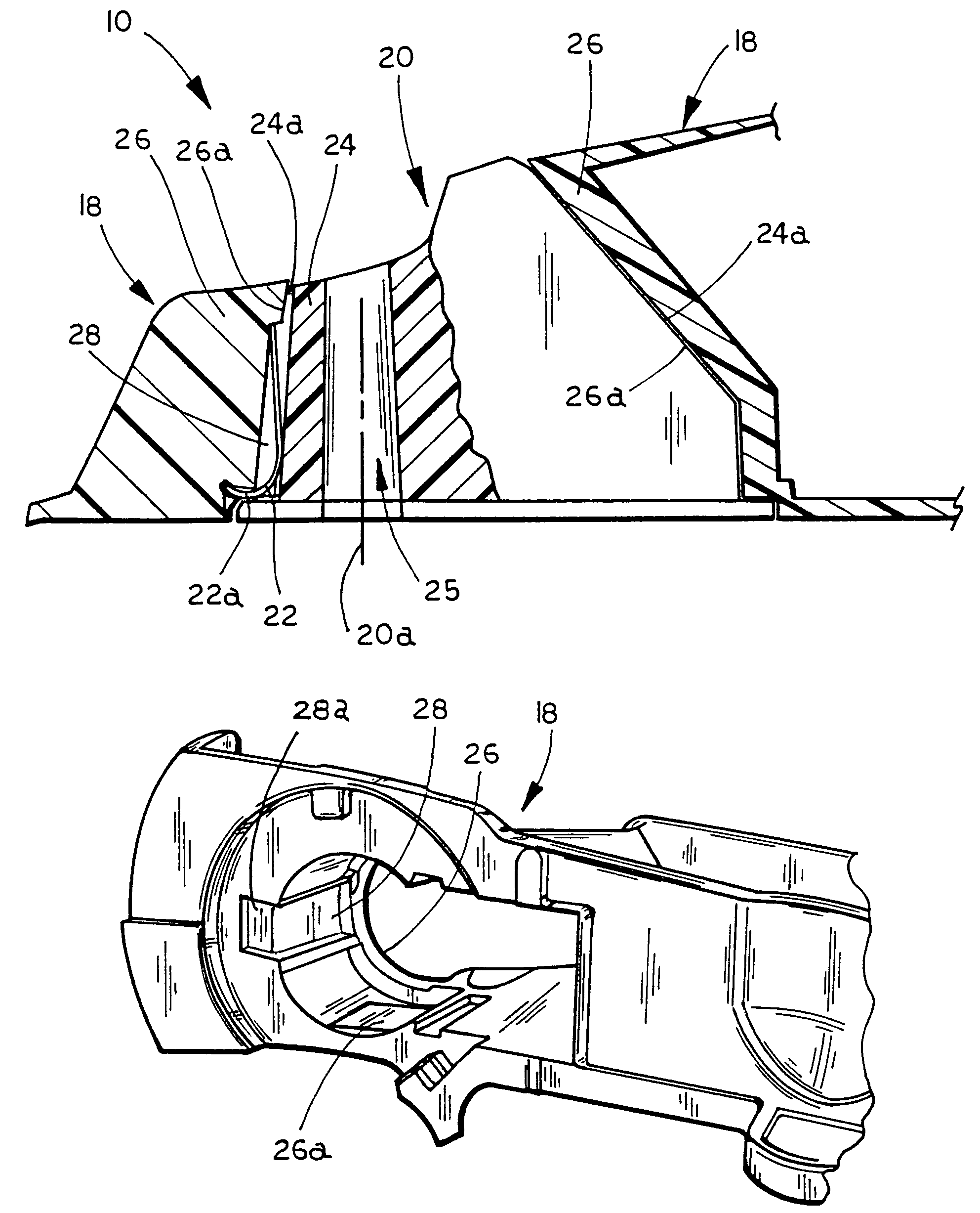
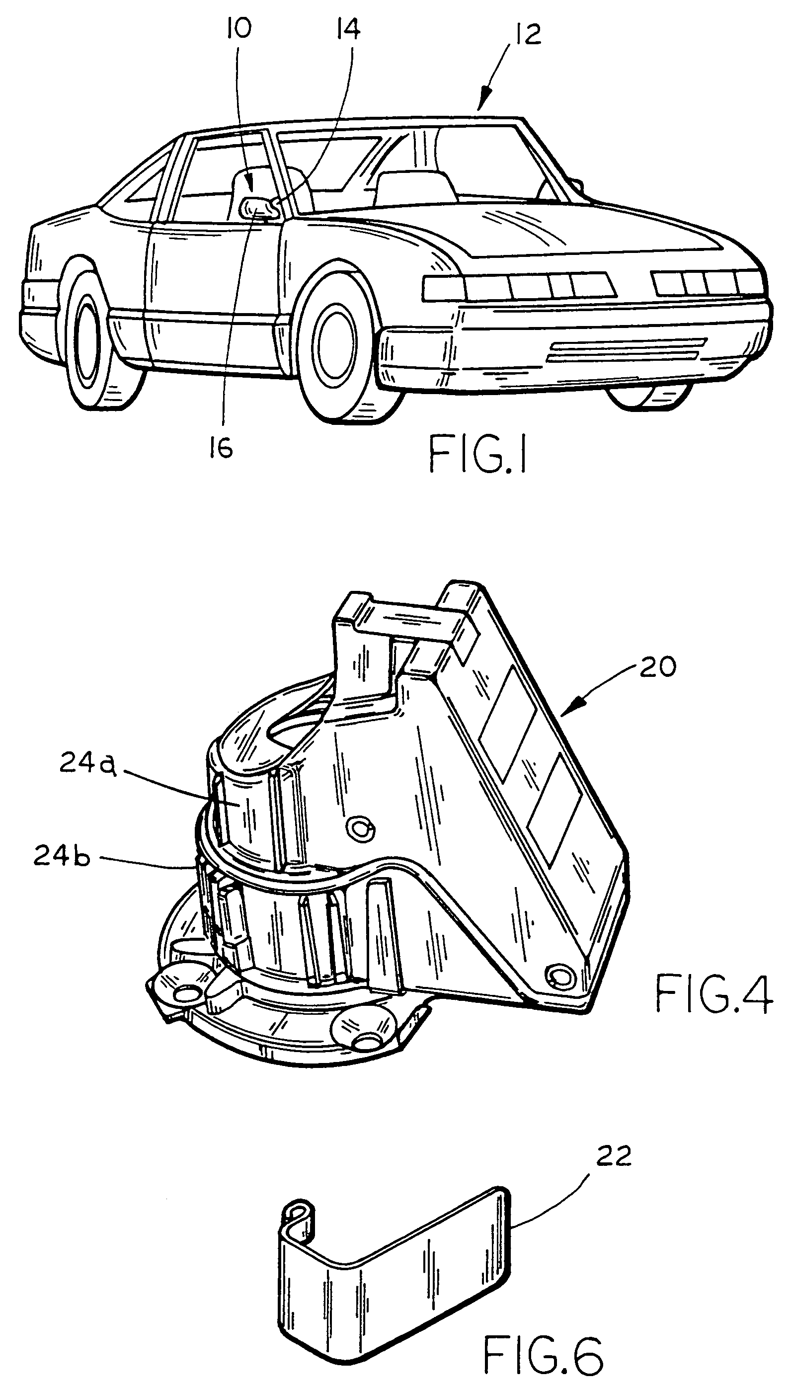
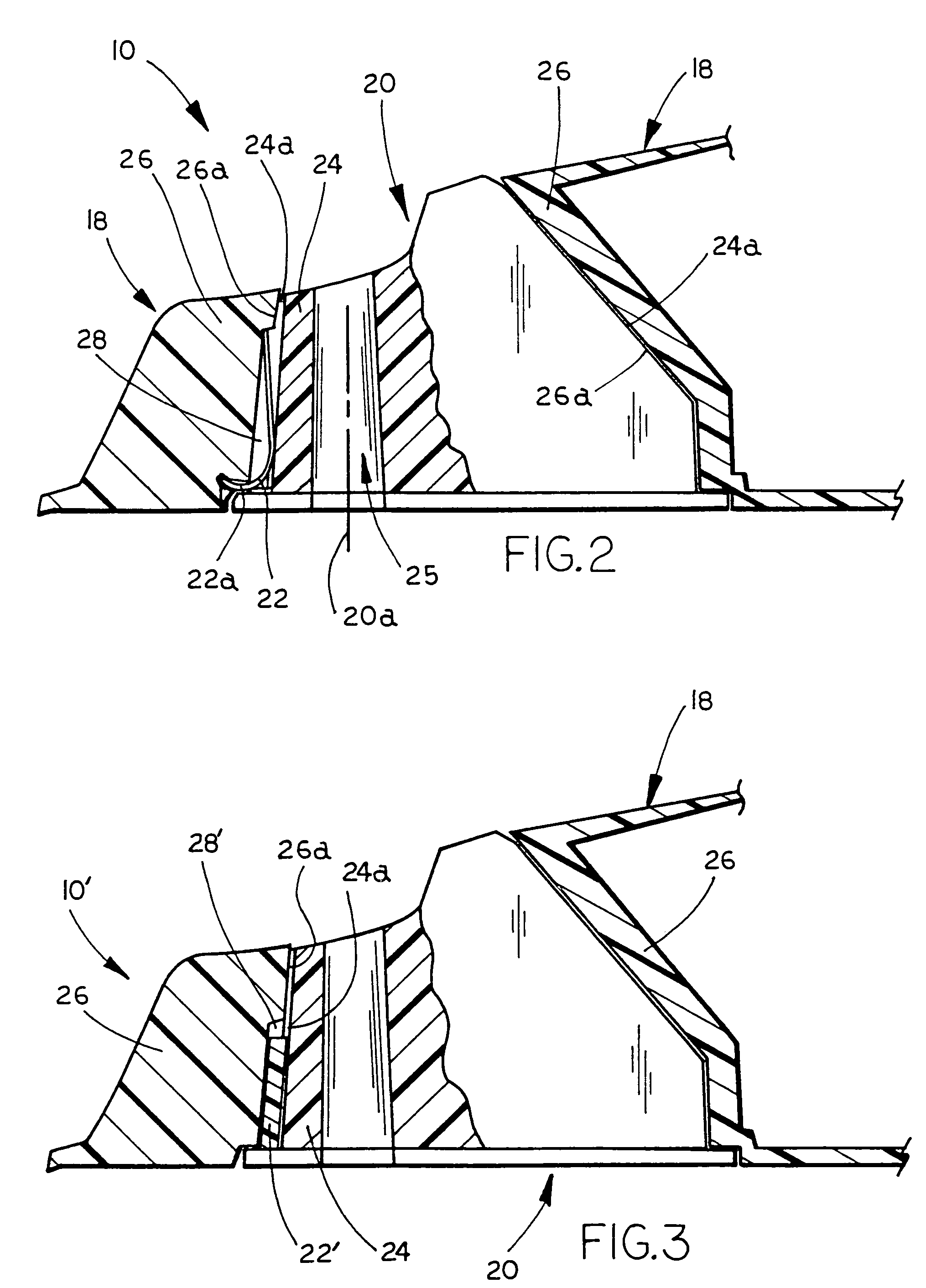
[0019]Referring now to the drawings and the illustrative embodiments depicted therein, a powerfold exterior rearview mirror assembly 10 is mounted to an exterior portion of one or both sides of a vehicle 12 (FIG. 1). Powerfold exterior mirror assembly 10 includes a generally fixed or non-movable base portion or mounting portion or sail portion 14, which is mounted to or affixed to the exterior portion of vehicle 12, and a head portion or movable portion 16, which is pivotally mounted to base portion 14. Head portion 16 of exterior rearview mirror assembly 10 includes a casing, which is secured to or attached to or mounted to a movable portion bracket 18 (FIGS. 2 and 3), and a reflective element (not shown) positioned at the casing. Head portion 16 and bracket 18 are movable or pivotable relative to fixed portion 14 by a motorized actuator or powerfold power pack or powerfold motor or unit or powerfold joint assembly 20 (FIGS. 2–4). A resilient element 22 is positioned between the po...


PUM


Abstract

An exterior rearview mirror assembly for a vehicle includes a base portion mounted to the vehicle and a movable portion that is pivotable relative to the base portion via a motor or motorized actuator or powerfold unit or the like. The powerfold unit is operable to pivot the movable portion relative to the base portion. The powerfold unit is mounted at one of the movable portion and the base portion and engages a receiving portion of the other of the movable portion and the base portion. A resilient element is positioned between and at least partially in engagement with the powerfold unit and the receiving portion. The resilient element is resilient and may at least partially compress as the powerfold unit is engaged with the receiving portion, thereby reducing or dampening vibration of the head portion relative to the base portion of the mirror assembly.

Description

CROSS REFERENCE TO RELATED APPLICATION[0001]The present application claims benefit of U.S. provisional application Ser. No. 60 / 501,186, filed Sep. 8, 2003, which is hereby incorporated herein by reference in its entirety.FIELD OF THE INVENTION[0002]The present invention relates generally to exterior rearview mirror assemblies for vehicles and, more particularly, to a powerfold exterior rearview mirror assembly which includes a movable portion or head portion and a motor or actuator that is operable to pivot the head portion relative to a base portion of the mirror assembly at the vehicle. The head portion is pivotable between a retracted or folded position and an extended or use position.BACKGROUND OF THE INVENTION[0003]It is well known in the automotive mirror art to provide a powerfold exterior rearview mirror assembly on a vehicle wherein a head portion or movable portion of the mirror assembly may be pivotable via a motor or power pack or actuator or the like, such that the mova...

Claims


Application Information

Patent Timeline
Patent Type & Authority Patents(United States)
IPC IPC(8): G02B5/08G02B7/18B60R1/074G02B7/182
CPCG02B7/182B60R1/074
Inventor BARVE, AMIT S.WEBER, RICHARD J.SHAPIN, ERICPAVAO, LEO W.
Owner DONNELLY CORP
Why Eureka
Try Eureka