Float type steam trap

a steam trap and floating technology, applied in the field of steam traps, can solve the problems of increasing f or lb>, increasing the size of the entire device, and reducing the discharge capability, so as to improve the valve closing performance, reduce the size of the device, and enhance the discharge capability

Inactive Publication Date: 2006-08-29
MOTOYAMASEISAKUSHO
View PDF7 Cites 15 Cited by
  • Summary
  • Abstract
  • Description
  • Claims
  • Application Information

AI Technical Summary

Benefits of technology

[0018]An object of the present invention is to provide a float type steam trap that can further improve the valve closing performance in a float type steam trap that achieves decreased size of device and enhanced discharging capability, improves the valve closing performance, and prevents the occurrence of water hammer.

Problems solved by technology

However, an increase in F or L1 presents a problem of increased size of the entire device.
Also, a decrease in A leads to decreased discharging capability, and a decrease in L2 leads to decreased discharging capability of condensate because a sufficient lift of inner valve cannot be provided.
Further, a decrease in ΔP restricts the service condition, and hence presents a problem of loss of versatility.
Therefore, the closing performance and durability are incomplete, and thus there arises a problem of steam leakage etc.
Also, the device in which the size thereof is small and the usable ΔP is large has low discharging capability.

Method used


Image

  • Float type steam trap
  • Float type steam trap
  • Float type steam trap

Examples


Embodiment Construction

[0064]FIGS. 1 to 12 show an embodiment of the present invention.

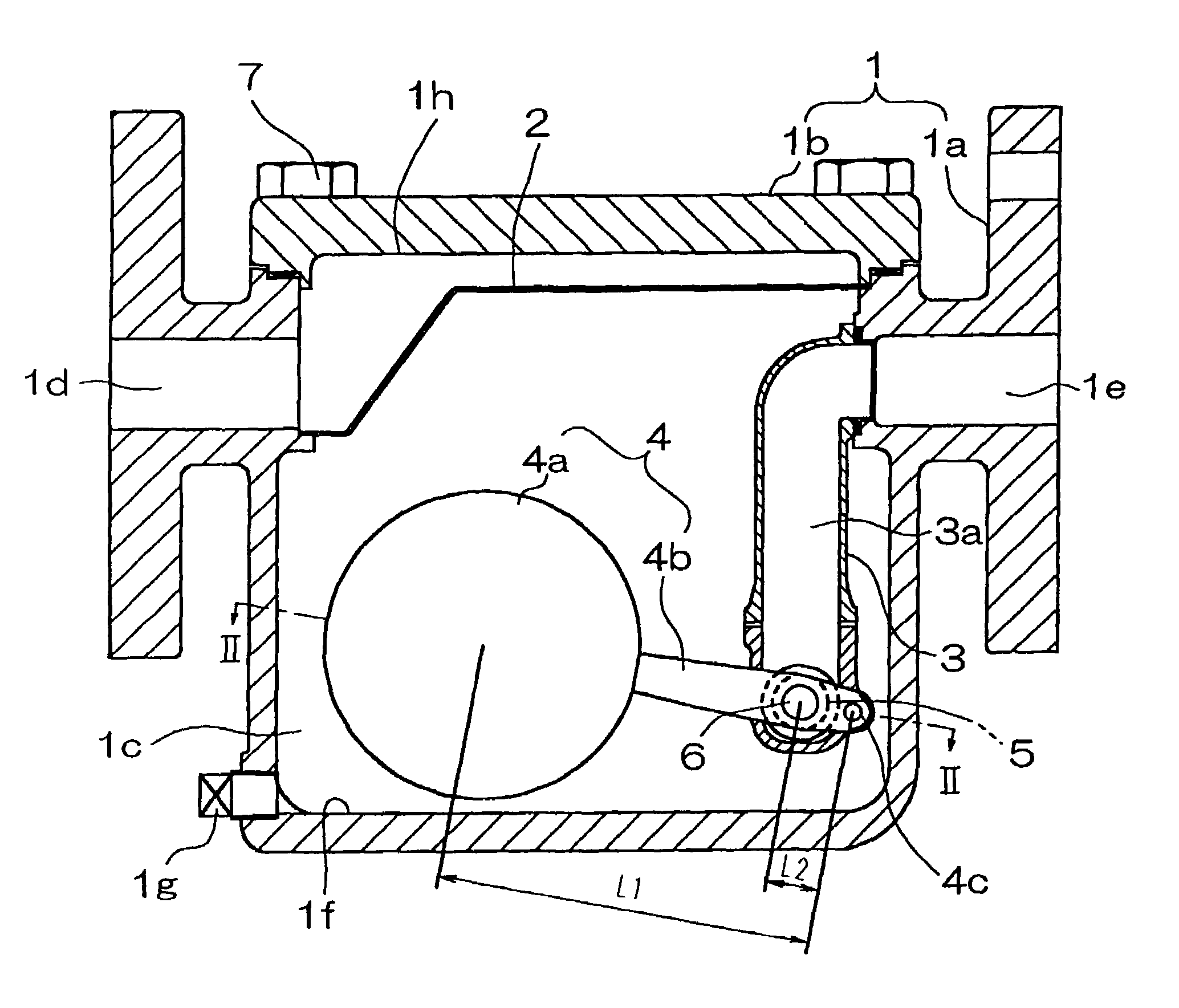
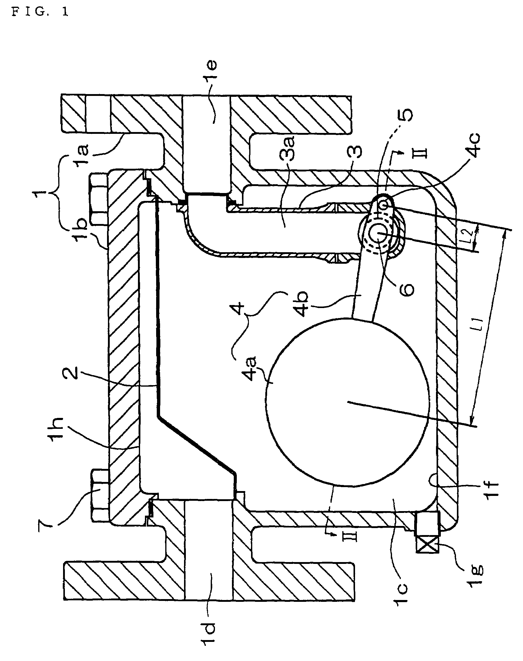
[0065]As shown in FIG. 1, a float type steam trap includes a casing 1, a strainer 2, a holder 3, a float 4, a valve seat 5, and a valve element 6. The casing 1 is constructed so that a cover 1b is threadedly engaged with a body 1a so as to be able to be opened and closed by using bolts 7.

[0066]The casing 1 has a float chamber 1c in the interior thereof, and also has an inflow port 1d and an outflow port 1e communicating with the float chamber 1c. The inflow port 1d and the outflow port 1e allow condensate to flow into and out of the float chamber 1c, respectively. A hole is formed in the side wall of the casing 1 at a position near a bottom 1f of the casing 1, and this hole is plugged with a plug 1g. The strainer 2 is provided on the inflow side of the float chamber 1c near an opening 1h of the body 1a to prevent foreign matters such as dirt from flowing into the float chamber 1c.

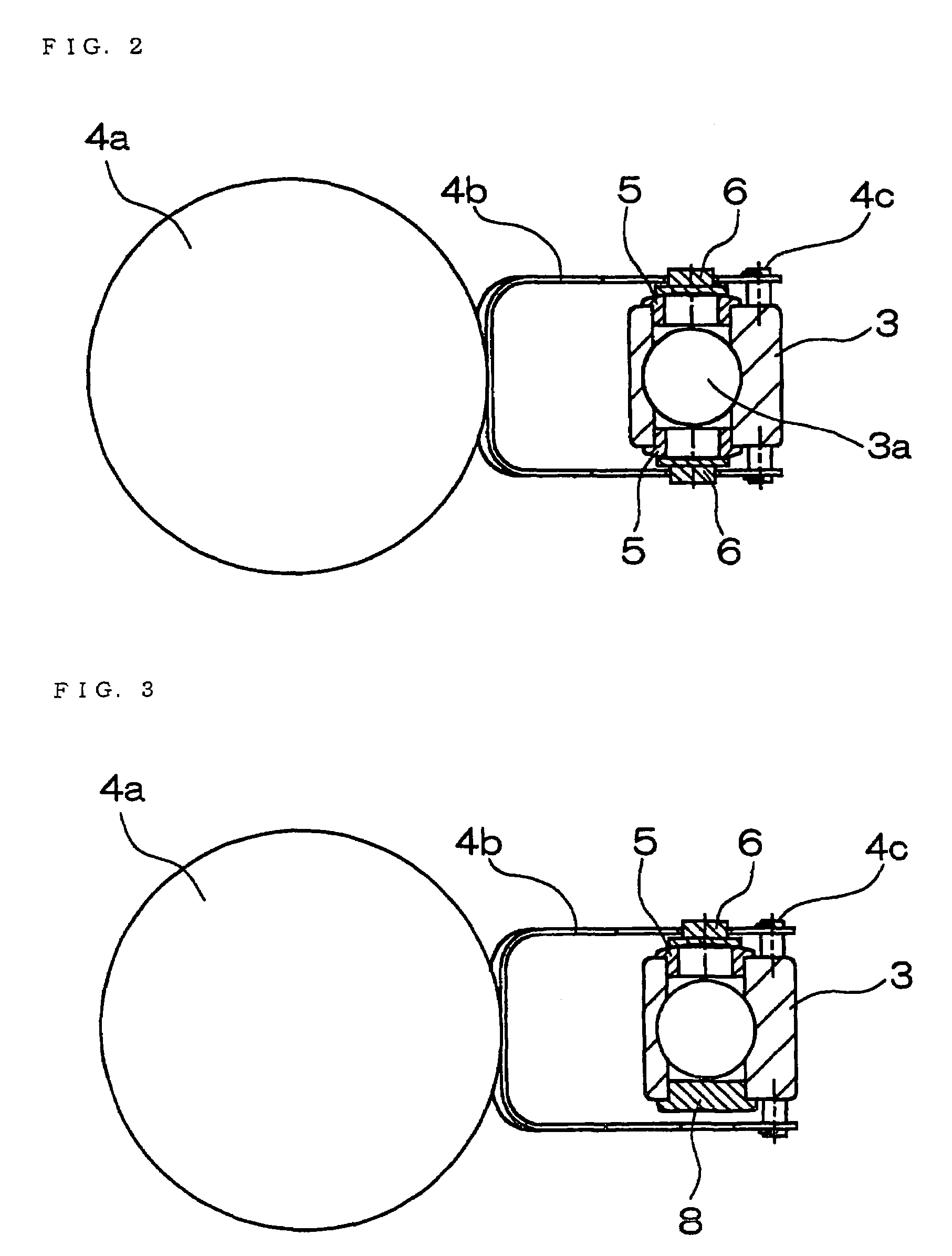
[0067]The holder 3 is of a tubular shap...


PUM


Abstract

There is provided a float type steam trap having a casing having a float chamber formed with an inflow port and an outflow port. A holder has a flow path communicating with the outflow port. A valve seat on the holder communicates with the outflow port. A float has a float body and a lever with a valve element. One end of the lever is fixed to the float body, and the other end is supported by the holder. The valve element slides with the up-and-down movement of the float body to open and close the valve seat 5.

Description

BACKGROUND OF THE INVENTION[0001]1. Field of the Invention[0002]The present invention relates to a steam trap which is connected to steam-operated equipment or steam tubes to automatically discharge condensate.[0003]2. Description of the Related Art[0004]A conventional float type steam trap is shown in FIGS. 13 and 14. A float type steam trap 50 shown in FIG. 13 is constructed so that a cylindrical inner valve 53 is fixed to a lever 52, one end of which is fixed and the other end of which is supported so as to be turnable, and the inner valve 53 moves up and down following the up-and-down movement of a float 51.[0005]Also, a float type steam trap 60 shown in FIG. 14 is constructed so that a spherical inner valve 63 is fixed to a lower end portion of a lever 62, one end of which is fixed to a float 61 and the other end of which is supported so as to be turnable, and the inner valve 63 is opened and closed along with the turning action of the lever 62.[0006]In the float type steam tra...

Claims


Application Information

Patent Timeline
Patent Type & Authority Patents(United States)
IPC IPC(8): F16T1/24
CPCF16T1/24Y10T137/7439Y10T137/3068
Inventor AOKI, MASAHIKOSANUI, JIRO
Owner MOTOYAMASEISAKUSHO
Why Eureka
Try Eureka