
Drive unit enclosure assembly

a technology for enclosures and drives, applied in the direction of superstructure subunits, propulsion parts, vehicle components, etc., can solve the problems of single piece hoods not providing adequate access to routine service points, floater-type agricultural applicators have drawbacks, and are too heavy and cumbersome for a single person, so as to improve ease and readiness

Active Publication Date: 2006-08-29
BLUE LEAF I P INC
View PDF15 Cites 18 Cited by
  • Summary
  • Abstract
  • Description
  • Claims
  • Application Information

AI Technical Summary

Benefits of technology

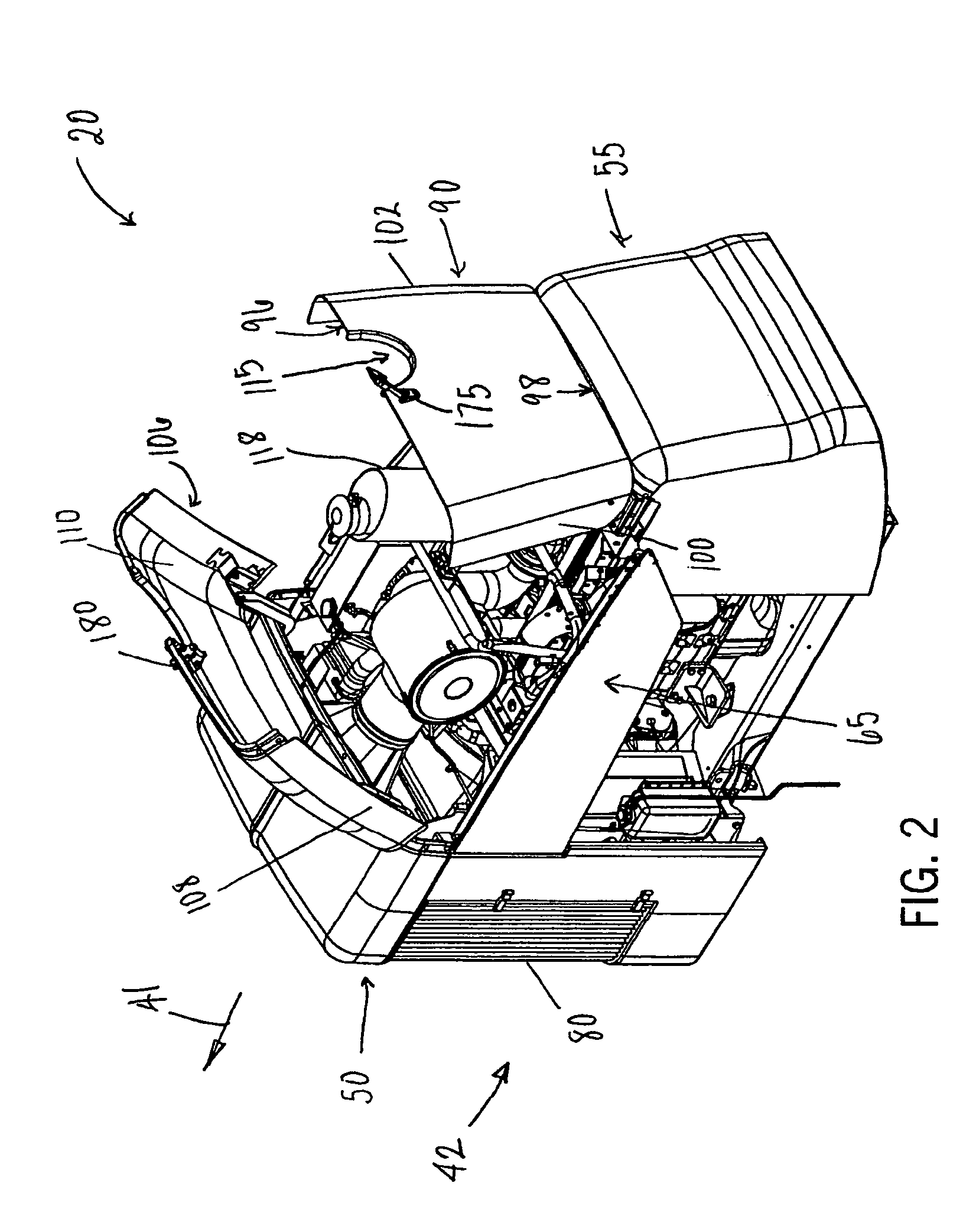
The present invention provides an enclosure assembly for a drive unit of an agricultural applicator. The enclosure assembly includes a first panel and a second panel that are pivotally connected to the housing of the applicator. The panels can be opened and closed to access the drive unit. The enclosure assembly also includes a first latch mechanism and a second latch mechanism to secure the panels in the closed position. The enclosure assembly is designed to improve ease and readiness in accessing and servicing the drive unit of the agricultural applicator.

Problems solved by technology

However, these floater-type of agricultural applicators have drawbacks.
The single piece hood generally does not provide adequate access to routine service points (e.g., air filter, oil level dipstick, engine valve backlash, etc.) of the drive unit.
In addition, the single-piece hood generally extends the length of the drive unit and therefore is too heavy and cumbersome for a single person to move between a closed position and an open position.
As with other known enclosures, the Johansson et al. vertical door and the structure of steps mounted thereon is heavy and cumbersome for a single person to move when accessing or servicing the motor.
Again, the Burgo hood does not provide ready access to routine service points (e.g., air filter, oil level dipstick, engine valve backlash, etc.) of the drive unit, and the hood is of a length that is heavy and cumbersome to move between an open and closed positions.

Method used


Image

  • Drive unit enclosure assembly
  • Drive unit enclosure assembly
  • Drive unit enclosure assembly

Examples


Embodiment Construction

[0021]A wide variety of vehicles could be constructed in accordance with the invention defined by the claims. Hence, while preferred embodiments of an enclosure in accordance with the invention will now be generally described with reference to a drive unit for a four-wheeled agricultural applicator, it should be understood that the invention is in no way so limited. The enclosure can be configured for any type of drive unit (e.g., hydraulic, pneumatic, mechanical, electrical, etc.) or combinations thereof of any type of mobile vehicle.

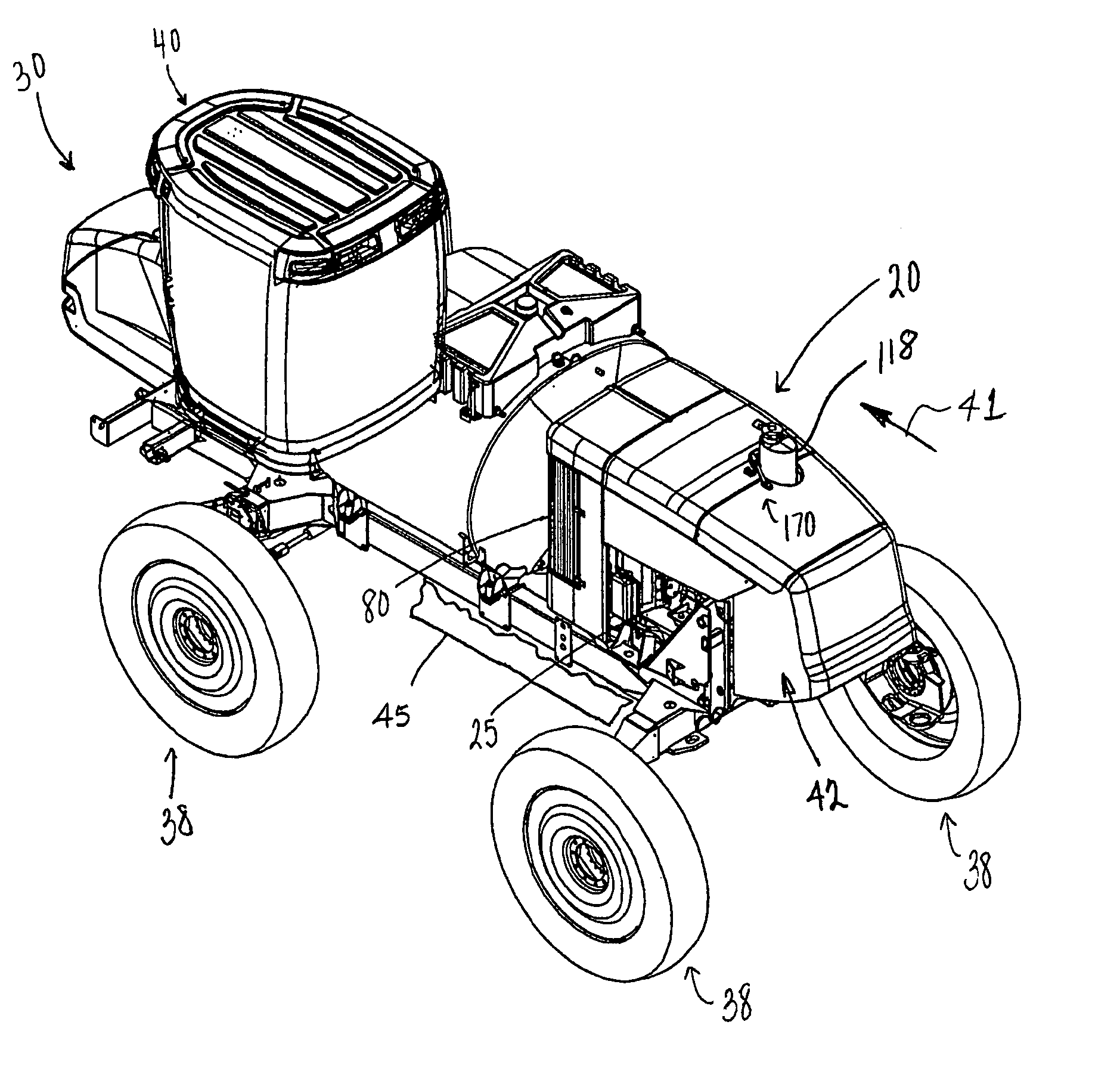
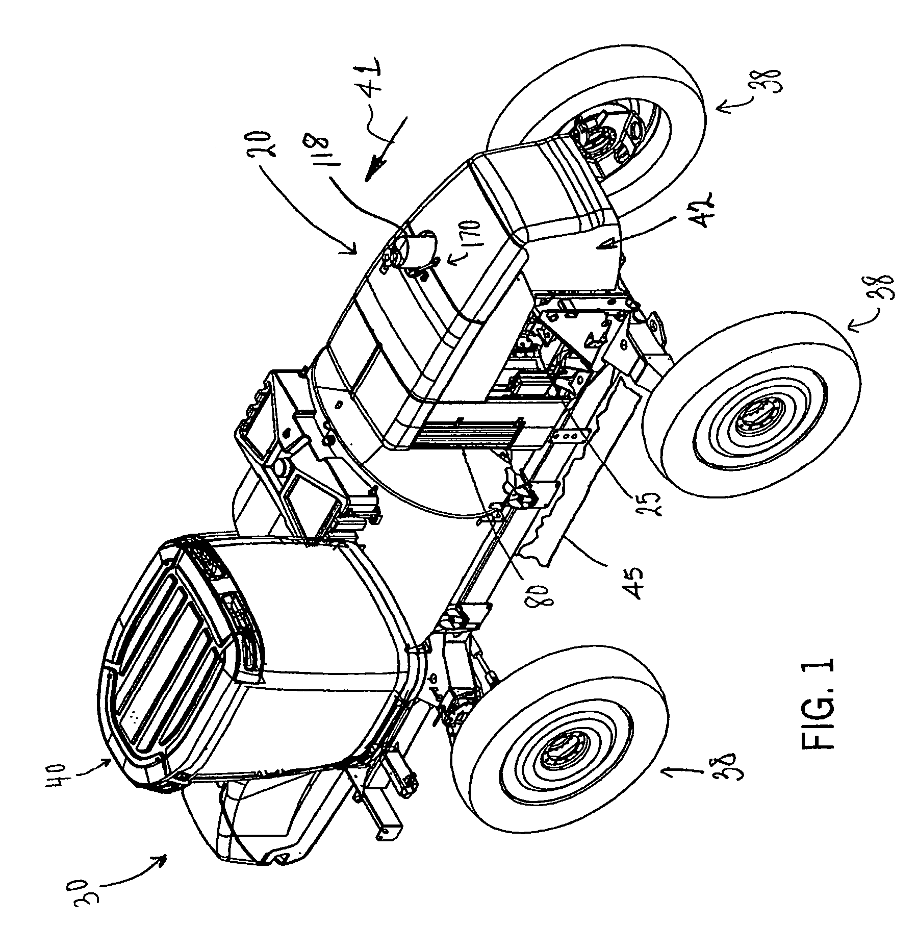
[0022]FIG. 1 illustrates an enclosure assembly 20 in accordance with the present invention enclosing a drive unit 25 of an agricultural applicator 30. The preferred agricultural applicator 30 includes a frame assembly 35 configured to support the drive unit 25 on a series of wheel assemblies 38. Although a four-wheeled agricultural applicator 30 is shown, it is understood that the number of wheel assemblies 38 can vary. The agricultural applicator 30 f...


PUM


Abstract

The invention provides an enclosure assembly configured to enhance accessibility to a drive unit of an agricultural applicator. The enclosure assembly generally includes a first panel and a second panel pivotally connected to the enclosure assembly and moveable between closed and open positions. In the closed position, the first panel is positioned in general alignment with the second panel. The enclosure assembly also accommodates an exhaust outlet extending upward from the drive unit. The forward end of the first panel includes a first cutout portion and the rearward end of the second panel includes a second cutout portion each configured in the closed position to receive the exhaust outlet. From the closed position, the first panel pivots in a rearward direction and the second panel pivots in a forward direction, relative to the forward direction of travel, to access the drive unit.

Description

FIELD OF INVENTION[0001]The invention relates to a drive unit enclosure assembly and, more particularly, to an agricultural applicator with a drive unit and an associated enclosure assembly having a first hinged panel and a second hinged panel configured to enhance access to the drive unit.BACKGROUND OF INVENTION[0002]Numerous types of agricultural applicators are available today. These can include a pull type unit or a self-propelled unit. A certain known agricultural applicator is also referred to a “floater.” The floater is a large vehicle that uses large, oversized floatation tires to carry the vehicle across firm to muddy agricultural environments. The chassis assembly of the floater generally includes three or more floatation tires. One particular chassis assembly includes a pair of rear floatation tires and a pair of front floatation tires. The chassis assembly is configured to support one or more bulk storage tanks or bins of product for application in an agricultural enviro...

Claims


Application Information

Patent Timeline
Patent Type & Authority Patents(United States)
IPC IPC(8): B62D25/10
CPCB62D25/10
Inventor MOEN, RICHARD A.LENT, KEVIN C.
Owner BLUE LEAF I P INC
Learn More