
Signature folding device

a folding device and signature technology, applied in the field of signature folding devices, can solve the problems of inexact folding, inconvenient folding, and inability to fit form-fittingly, and achieve the effects of stable guidance of signatures, and stable guidan

Inactive Publication Date: 2006-08-29
GRAPHA HLDG AG
View PDF6 Cites 6 Cited by
  • Summary
  • Abstract
  • Description
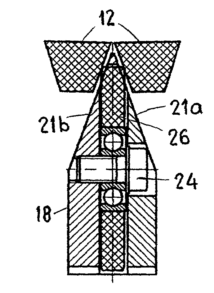
  • Claims
  • Application Information

AI Technical Summary

Benefits of technology

[0006]Thus, it is an object of the invention to provide a folding device of the aforementioned type, which permits a more precise folding, but which can nevertheless be produced easily and cost-effectively and is robust.
[0008]With this type of folding device, a precise, saddle-shaped and continuous folding line can be formed at the folding sword. The inside guide element is arranged at the location where the outside folding element grips and transports the signature. As a result, the signature to be folded is guided definitively and continuously and the signatures are prevented from slipping off the folding sword, which is undesirable.
[0009]According to a modification of the invention, the inside guide element is designed so that it projects from the guide surfaces on the side of the folding sword. As a result, the side regions in which the signatures are guided can be exactly determined. If, according to another modification of the invention, the folding sword is tapered in the movement direction, at least in a frontal area, the signatures can be mostly closed and the folding sword can still have a robust design. Several rollers aligned in a row advantageously form the guide element on the inside. These are preferably arranged such that they project with at least one outside edge on the side at the guide surfaces of the folding sword. A particularly good guidance is achieved if the roller surface on at least one edge is essentially parallel to one guide surface on the side of the folding sword.
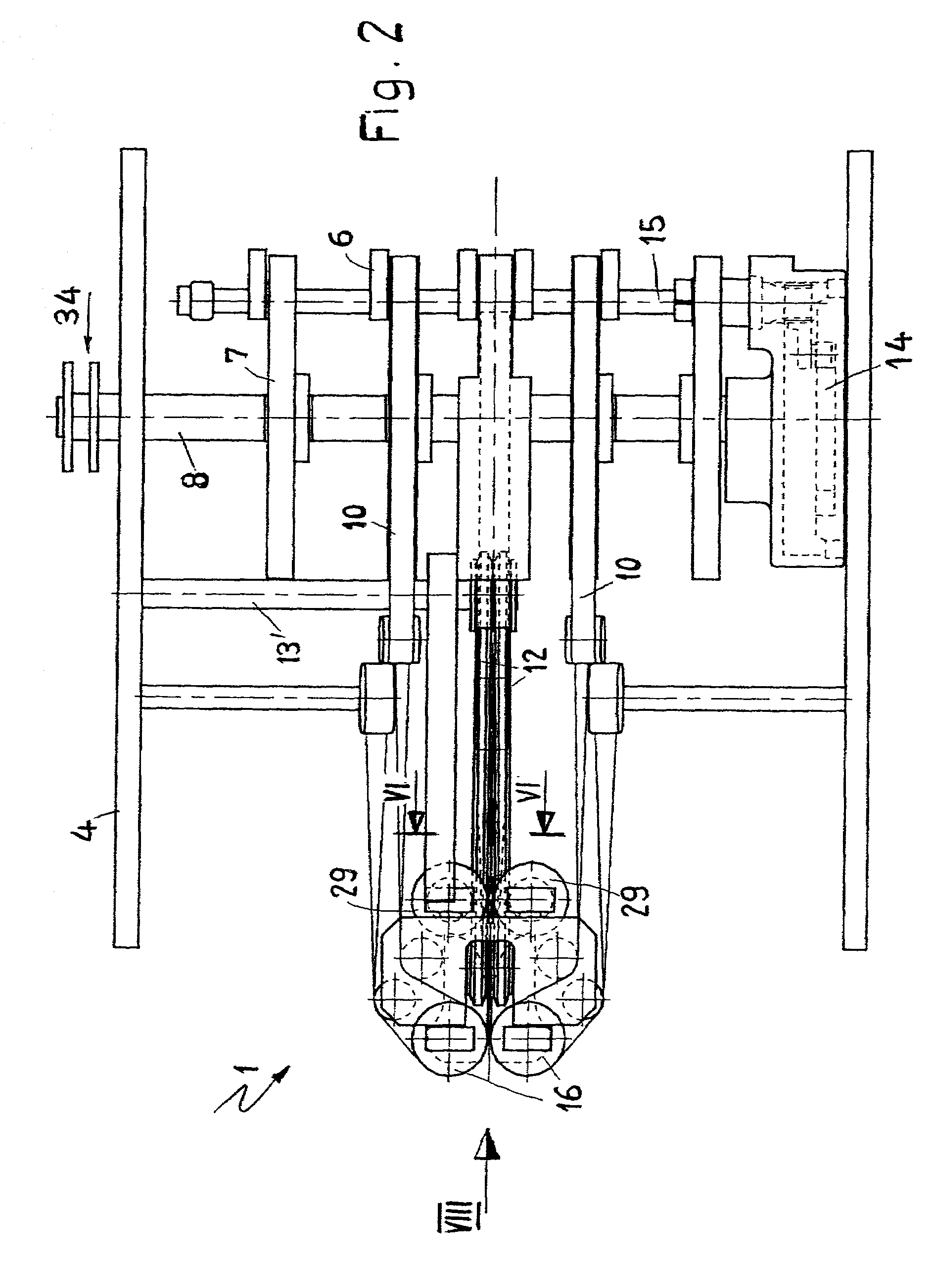
[0011]A particularly stable guidance of the signatures is achieved if these V-belts are not simply adjusted to feed to the folding sword, but if they are twisted along the folding sword, in accordance with the feeding. This results in a very stable guidance of the signatures during the folding operation, which are stretched over the edge of the folding sword. The signatures consequently have a stable guidance over the complete region of the folding sword and are effectively prevented from sliding off or otherwise deviating from the predetermined path.

Problems solved by technology

A folding design of this type has the particular disadvantage that the folding occurs only gradually and that the signatures do not fit form-fittingly against the folding sword until the end of the folding operation.
Prior to this, the signatures are quite unstable and can deviate from the predetermined course, thus resulting in an inexact folding.
Another difficulty is that the signatures to be folded are slowed down on the inside, by the folding sword that is stationary, and at best have a tendency toward smearing.
These two requirements conflict with each other, so that compromises are necessary in the one or the other direction.
If the folding element on the inside consists of rollers, arranged one behind the other as specified in the Swiss Patent, the difficulty arises that during the folding process the front edges of the signatures to be folded must repeatedly run in via the subsequent roller.
If the signatures to be folded are not always positioned exactly the same way for the run in, the resulting fold is not sharp and the folding accuracy cannot meet high requirements.
A precise run in of the signatures onto the rollers is difficult to realize since stresses in the signatures to be folded are hard to avoided during the process of folding the signatures while they are passing through.

Method used


Image

  • Signature folding device
  • Signature folding device
  • Signature folding device

Examples


Embodiment Construction

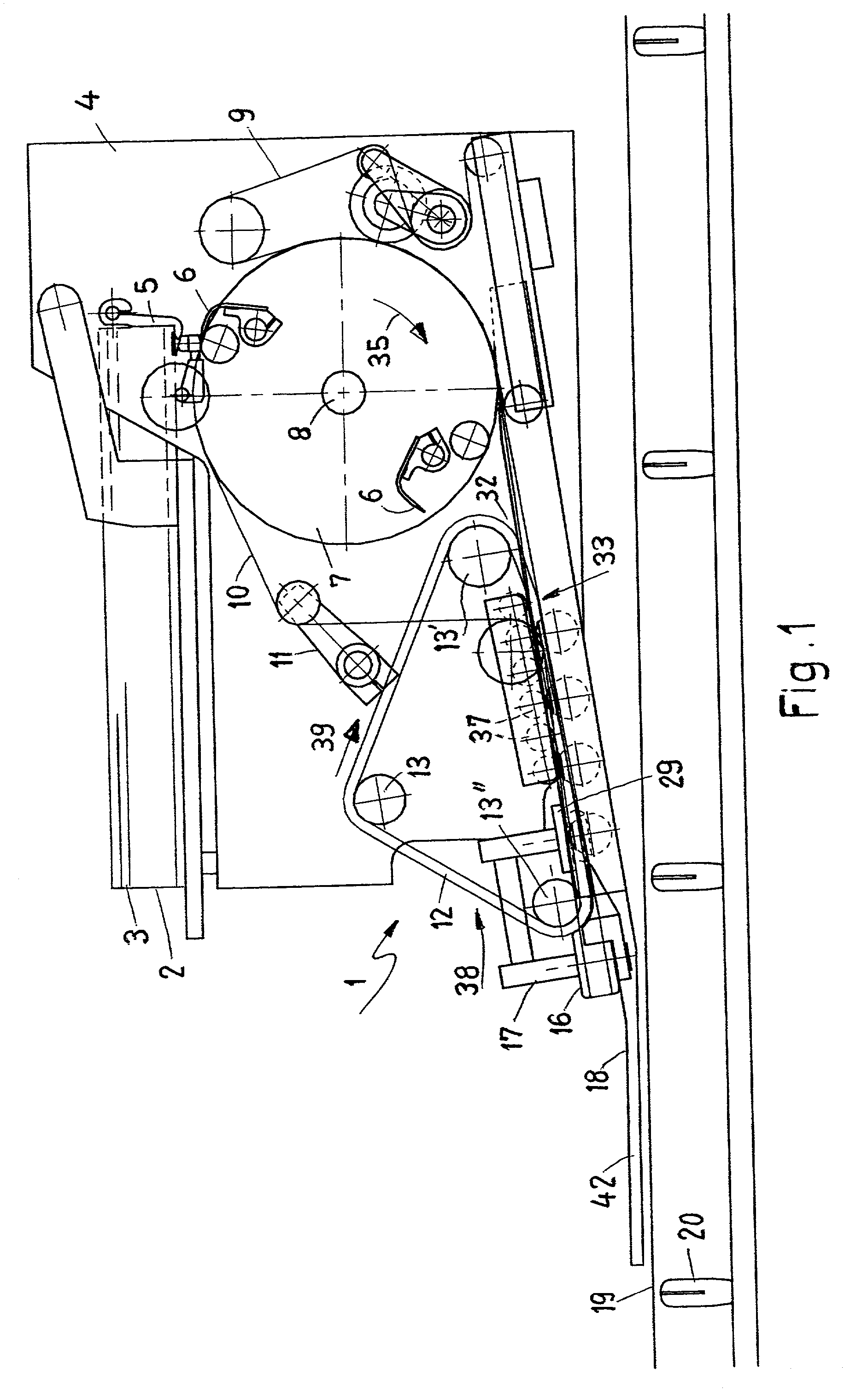
[0023]Referring to FIG. 1, signatures 3 to be folded are initially stacked one above the other to form a stack 2. The lowest signature 3 is respectively tilted with the aid of a suction device 5 from the stack 2 into a gripping region of a gripping drum 7. Gripping drum 7 has grippers 6 that respectively grip one tilted signature 3 and pull this signature from stack 2. The pulled-off signature 3 can be notched with the aid of a notching wheel, not shown herein, or can be otherwise weakened or processed, for example by moistening it, in order to prepare the fold. The pulled-off signatures 3 are respectively guided individually with the aid of transfer belts 9 and 10 to a run-in 32 of a folding section 33. A folding sword 18, two endless strands 12 and two pressing rollers 16 essentially form folding section 33.

[0024]A shaft 8 drives gripper drum 7 in the direction of arrow 35 and a drive element 34 drives the shaft 8. The transfer belts 10 are driven by the gripper drum 7 and are gui...


PUM

PropertyMeasurementUnit
Shapeaaaaaaaaaa

Abstract

A folding device for signatures includes a saddle-shaped folding sword having an upright folding edge and an inside guide element below the upright folding edge on which the signatures are folded while passing through the folding device. An outside folding element follows and operates jointly with the inside guide element for folding the signatures.

Description

CROSS REFERENCE TO RELATED APPLICATION[0001]This application claims the priority of European Patent Application No. 01810320.0 filed in the European Patent Office on Mar. 29, 2001, the disclosure of which is being incorporated herein by reference.BACKGROUND OF THE INVENTION[0002]The invention relates to a signature folding device, comprising a saddle-shaped folding sword with an inside guide element on which the signatures are folded. The device furthermore comprises an outside folding element that follows along and operates jointly with the inside guide element for folding the signatures.[0003]Folding devices of the aforementioned type are known. With these devices, the signatures to be folded are guided onto a stationary folding sword and are folded thereon while passing through, with the aid of the outside folding element that follows. Belts, round strings, V-belts or chains, for example, can form the folding element that follows. A folding design of this type has the particular ...

Claims


Application Information

Patent Timeline
IPC IPC(8): B31F1/00B65H45/18B65H45/22
CPCB65H45/22
Inventor MERKLI, PETER
Owner GRAPHA HLDG AG
Learn More