Conductor clamp for a trailing line

Inactive Publication Date: 2009-01-29
CONDUCTIX WAMPFLER
View PDF10 Cites 4 Cited by
  • Summary
  • Abstract
  • Description
  • Claims
  • Application Information

AI Technical Summary

Benefits of technology

[0005]The present invention is based on the task of providing a solution for damping the impact of the first crab of a trailing line on its conductor clamp, wherein this solution is distinguished by effectiveness according to the requirements with a simple construction.
[0008]It is especially useful to arrange a resilient spring body at the end of the shock absorber, wherein this spring body is provided for introducing an impact force, so that this spring body can take over the damping essentially by itself for an impact of low intensity, without other components of the shock absorber being significantly deflected.
[0010]The arrangement of at least two similar spring bodies one next to the other in the housing, to which the total effective force is distributed at least approximately uniformly, permits an especially compact construction of the shock absorber and a stable guidance of its moving components in the case of a deflection.

Problems solved by technology

However, the conductor clamp, which secures one end of the trailing line to one end of the carrier rail, is mounted stationary on the carrier rail and cannot yield by means of its own movement, when the first crab impacts against it with the return movement of the trailing line.

Method used


Image

  • Conductor clamp for a trailing line
  • Conductor clamp for a trailing line
  • Conductor clamp for a trailing line

Examples


Embodiment Construction

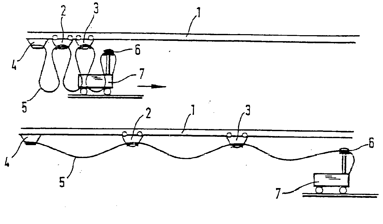
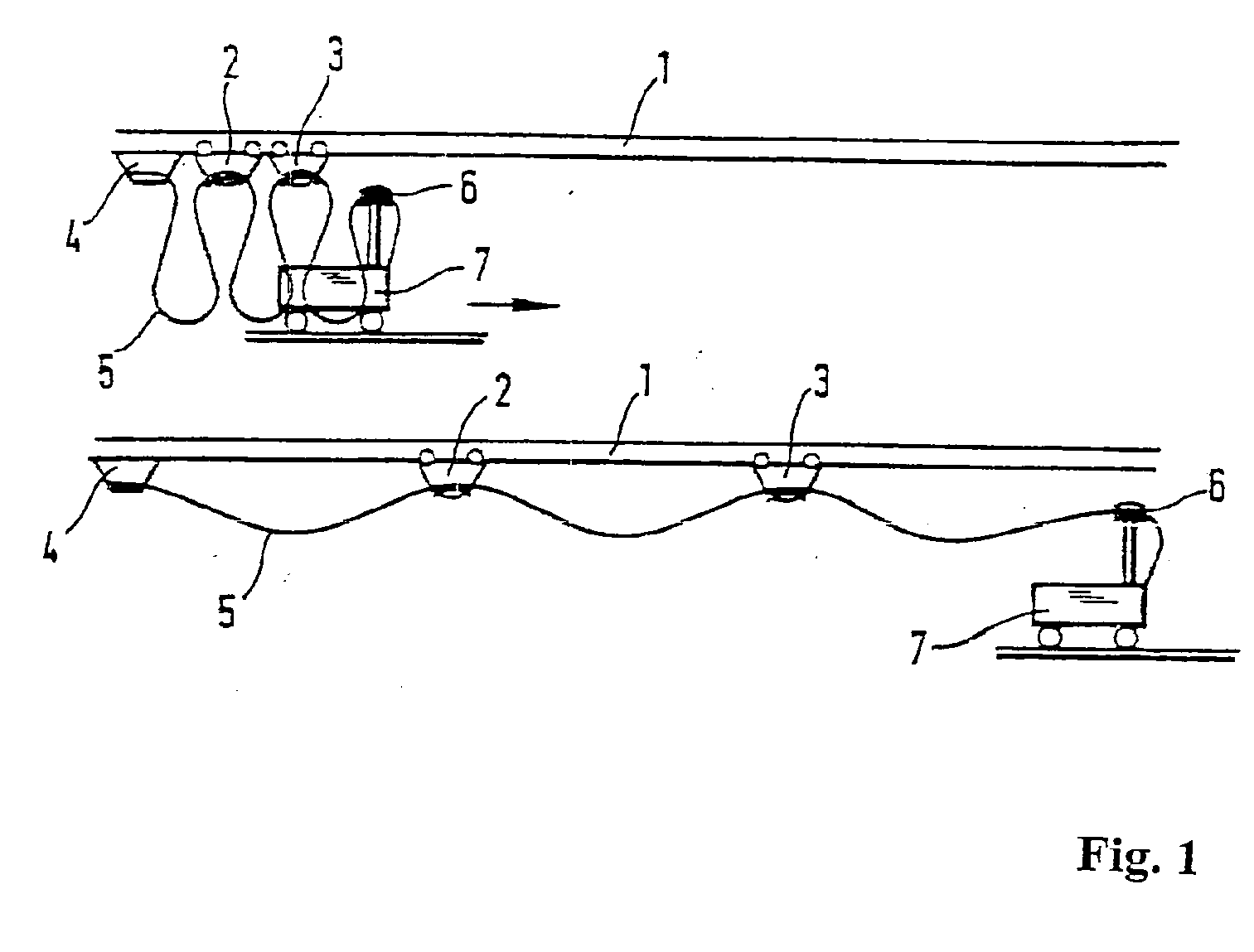
[0017]As shown schematically in FIG. 1, in a trailing line system, several moving crabs 2 and 3 are guided on a carrier rail 1, wherein their number is generally significantly larger than two. Starting from a conductor clamp 4 mounted rigidly on one end of the carrier rail 1, one or more lines 5, for example, electrical lines, are guided via the crabs 2 and 3 to a line clamp 6 of a moving work device 7, for example, a derrick car. Because the crabs 2 and 3 can collide with each other in the course of their movements following the work device 7 along the carrier rail 1, they are equipped with shock absorbers that are not shown in FIG. 1. These shock absorbers do not need to have a very resilient construction, because the crabs 2 and 3 can also yield due to their own movement when there is an impact. However, this does not apply for the conductor clamp 4, which would be subjected to relatively large vibrations when the trailing line is moved back into the starting position shown at th...


PUM


Abstract

A conductor clamp (4) for a trailing line (5) which is secured to crabs (7) which can be moved along a carrier rail (1) comprises a support (8) for the trailing line, a clamping device (9) for securing the trailing line to the support and a shock absorber (10) for absorbing an impact of the first crab on the conductor clamp. The shock absorber has at least two spring bodies (20, 22) which have different characteristics and which are arranged one behind the other in the anticipated direction of action of the shock absorber. In this context, the most resilient spring body (20) is arranged closest to the end of the shock absorber which is provided for the application of an impact force. The shock absorber also has a lifting rod (16) which can be displaced under the effective impact force in the anticipated direction of action of the shock absorber. At the two ends of the lifting rod, spring bodies with different characteristics are arranged. The shock absorber has a housing in which the lifting rod is movably mounted, with an internal end of the lifting rod being located inside the housing, and an external end of said lifting rod being located outside the housing.

Description

FIELD OF THE INVENTION[0001]The invention relates to a conductor clamp for a trailing line according to the preamble of Claim 1. Such a conductor clamp is used for securing one end of a trailing line to one end of a carrier rail, along which the trailing line can be towed by means of several crabs. For this purpose, the conductor clamp is mounted stationary on the carrier rail.BACKGROUND OF THE INVENTION[0002]In the course of the movement of the trailing line, when the crabs are moved away from each other, tensile forces must be transmitted between the individual crabs and, when the crabs are moved toward each other, compressive forces must be transmitted between the individual crabs, wherein the loading takes place abruptly and therefore high peak values of the forces occur if countermeasures are not taken. For this purpose, DE 1 193 333 A provides coil springs on the crabs, wherein these springs are arranged in cylinders and are compressed by pistons running in the cylinders both ...

Claims


Application Information

Patent Timeline
IPC IPC(8): H02G11/02
CPCH02G11/003H02G11/00
Inventor MAIER, BERND
Owner CONDUCTIX WAMPFLER
Why Eureka
Try Eureka