ECM-machine

Inactive Publication Date: 2009-03-10
LEISTRITZ TURBOMASCHEN TECHN
View PDF4 Cites 3 Cited by
  • Summary
  • Abstract
  • Description
  • Claims
  • Application Information

AI Technical Summary

Benefits of technology

[0005]It is therefore an object of the invention to indicate an ECM machine, which permits flexible machining even of different workpieces of different geometry with, at the same time, a high machining accuracy.
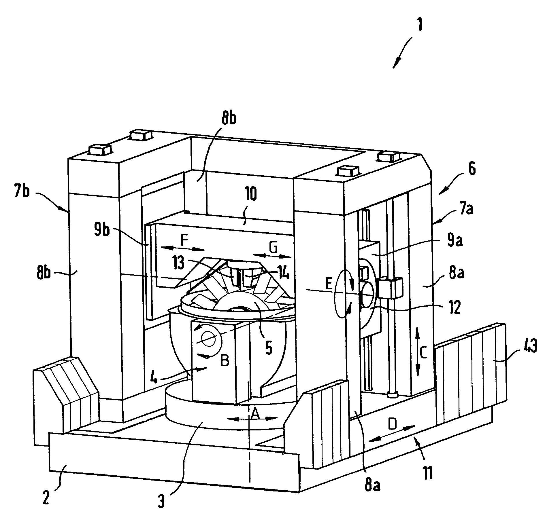
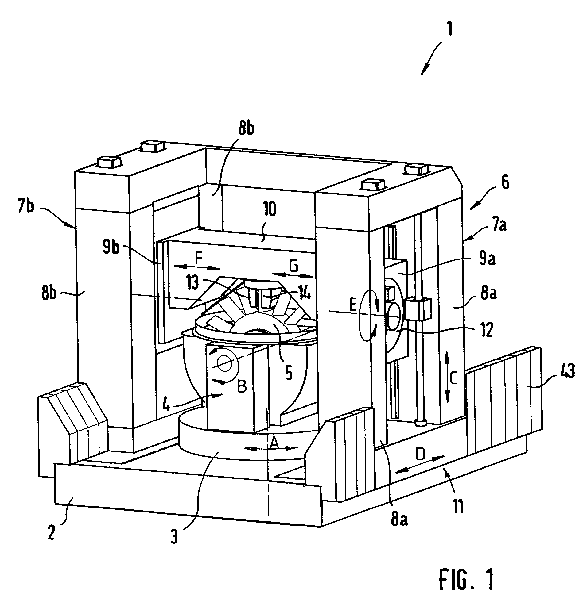
[0012]The inventive ECM machine is distinguished by the use of a portal, at which a transverse girder is disposed vertically movably and, in turn, carries the cathodes. A symmetrical construction is realized. The vertical guidance of the horizontal girder leads to maximum stiffness and, at the same time, minimizes thermal effects. At the same time, long traveling paths can be achieved. Because of the different axes and mobilities, which have been provided, it is also possible to machine workpieces with complicated spatial shapes. As described, the workpiece itself is disposed at a revolving table, which can be rotated about a vertical axis. The portal can be shifted horizontally with respect to table and, with that, with respect to the workpiece. The cathodes themselves can also be moved vertically with respect to the workpiece. The portal can be moved horizontally with respect to the table and, with that, with respect to the workpiece. The cathodes themselves can also be moved vertically with respect to the workpiece and can be rotated into any angular position because of the rotatable arrangement of the transverse girder about a horizontal axis. One or two further movement axes may furthermore be realized owing to the fact that the two cathodes can be moved jointly at a common horizontal guide or that each cathode can be shifted separately at a horizontal guide at the transverse girder. Alternatively, in the case of simpler objects, it is also conceivable to provide, instead of the cathode guides at the transverse girder, only one clamping device for a mold, namely when a horizontal movement in this area is not required. Alternatively, it is, of course, also conceivable to dispose the clamping device itself horizontally movably at the transverse girder.
[0013]On the whole, because of the relative mobility of the individual elements with respect to one another, the inventive ECM machine offers a high degree of flexibility with respect to the mobility of the parts and permits parts of different geometry (cylindrical, prismatic, polygonal, panel-shaped or disk-shaped, etc.), to be machined. Moreover, because of the construction of the portal, maximum stiffness and, with that, extremely high accuracy are ensured. Advantageously, the accuracy and positioning problems, resulting from the “open” construction of the aforementioned state of the art, do not arise in the case of the inventive machine. A further advantage is the good accessibility to the working area, since, because of the horizontal mobility of the whole portal, at which the working components are provided, the revolving table and, with that, the workpiece mount are easily accessible. This means that, because of the long portal traveling path that can be realized, the workpiece is a readily accessible. The corresponding applies also for the workpiece cathodes, which, with appropriate positioning of the portal remote from the revolving table, are also readily accessible, so that an exchange is possible very easily here as well as at the revolving table.
[0015]In the event that a workpiece carrier with an integrated, horizontal axis of rotation is provided, an advantageous further development of the invention provides for configuring said workpiece carrier so that the workpiece can be displaced linearly along the horizontal axis of rotation. This configuration makes it possible to clamp and machine rotors with several rows of blades, so-called multiple blisks. Because of the linear displaceability, it is possible to position the vertical axis of each of the blade rows, which are to be processed and are aligned with the axis of rotation of the table, in order to be able to load the cathodes, for which purpose, because of the fact that the blade shape is wound in itself, the revolving table must be rotated somewhat during the loading motion. With this configuration of the invention, the spectrum of work can be enlarged even further.
[0022]Even though they are not described in greater detail, measurement sensors for accurately determining the path of the rotational or longitudinal driving mechanisms, the movement of which is numerically controlled and which can be triggered separately, are of course provided at the machine and placed or integrated at the appropriate site. Signal leads are also always placed so that they do not ever interfere either during the actual machining operation or within the scope of other movements.

Problems solved by technology

Advantageously, the accuracy and positioning problems, resulting from the “open” construction of the aforementioned state of the art, do not arise in the case of the inventive machine.

Method used


Image

  • ECM-machine
  • ECM-machine
  • ECM-machine

Examples


Embodiment Construction

[0032]FIG. 1 shows an inventive ECM machine 1 with a machine bed 2 and a revolving table 3, on which the workpiece or workpiece carrier is mounted. The revolving table 3 can be rotated about a vertical axis A, as indicated by the double arrow A.

[0033]A fork-shaped workpiece carrier 4, which can be rotated by the revolving table 3, is fastened to the revolving table 3. A clamping device, which will be dealt with in the following and with which the workpiece, which in this case is a bladed rotor 5, can be clamped, is integrated at the workpiece carrier 4. The clamping device enables the clamped workpiece to be rotated about a horizontal axis of rotation B, as indicated by the double arrow B.

[0034]Furthermore, a portal 6 is shown, which consists of a right portal section 7a and a left portal section 7b. Each portal section 7a, 7b has two vertical columns 8a and 8b, which are connected at the top and bottom with girders to form a closed frame. The columns form the guides for in each cas...


PUM

PropertyMeasurementUnit
Poweraaaaaaaaaa

Abstract

ECM machine for electrochemically machining metallic workpieces by anodic dissolution of the workpiece by means of an electrolyte and an applied dc voltage, comprising at least one revolving table for mounting the workpiece or a workpiece carrier, as well as a portal with a transverse girder, at which one or two cathodes are provided, the at least one revolving table being rotatable about a vertical axis and being movable along horizontal guides linearly with respect to the revolving table. The transverse girder is movable vertically at vertical guides of the portal, transverse girder being rotatable about a horizontal axis of rotation. The cathode or cathodes are clampable each at one or at a common clamping device at the transverse girder and / or movable linearly along the transverse girder at least at one horizontal guide.

Description

BACKGROUND OF THE INVENTION[0001]The invention relates to an ECM machine for electrochemically machining metallic workpieces by anodic dissolution of the workpiece by means of an electrolyte and an applied dc voltage.[0002]The principle of ECM machining (ECM=Electro Chemical Machining) is based on the fact that a direct current is applied between a mold and the workpiece, which is to be machined. This direct current is sufficient to bring about a uniform, anodic dissolution of the workpiece in a region in the vicinity of the latter. In the gap between the workpiece and the mold (cathode) a suitable electrolyte solution flows continuously at a high rate. A copying of the contour of the mold is achieved by moving the workpiece forwards in a controlled manner. The ECM method works without the action of a mechanical force between the workpiece and the mold, which is not subjected to any wear. A very high copying accuracy and repetition accuracy is achieved and it is possible to produce ...

Claims


Application Information

Patent Timeline
IPC IPC(8): C25D17/00
CPCB23H3/00B23H7/26B23H9/10B23H11/003
Inventor SCHMIDT, GEORG
Owner LEISTRITZ TURBOMASCHEN TECHN
Why Eureka
Try Eureka