
Modular femoral stem component for a hip joint prosthesis

a hip joint and femoral stem technology, applied in the field of orthopaedic prostheses, can solve the problems of difficulty in providing the correct femoral stem component for patients, the distal section of the prosthesis may not be appropriately sized for proper seating in the distal section of the femur, and achieve the effect of restoring the hip join

Inactive Publication Date: 2006-08-29
DEPUY PROD INC
View PDF30 Cites 31 Cited by
  • Summary
  • Abstract
  • Description
  • Claims
  • Application Information

AI Technical Summary

Benefits of technology

[0014]Still another object of the present invention is to provide an improved method for restoring a hip joint.

Problems solved by technology

However, despite this, it has been found that it can be difficult to provide the correct prosthetic femoral stem component for patients.
This is due to the wide variation in patient anatomies and to the practical limitations of hospital inventory.
By way of example, where a femoral component is selected having a proximal section appropriately sized for the proximal section of the resected femur, the distal section of the prosthesis may not be appropriately sized for proper seating in the distal section of the femur.
This can present serious problems for the patient, including problems relating to joint stability and pain.
While different types of modular connections are known in the art, no one modular connection is ideal for dealing with all three types of loads, i.e., axial, bending and torsional loads.
By way of example, taper connections generally accommodate axial (i.e., compressive) loads well, but they generally do not accommodate bending and torsional loads particularly well.
By way of further example, concentric cylinder connections generally accommodate bending loads well, but they generally do not accommodate axial and torsional loads particularly well.

Method used


Image

  • Modular femoral stem component for a hip joint prosthesis
  • Modular femoral stem component for a hip joint prosthesis
  • Modular femoral stem component for a hip joint prosthesis

Examples


Embodiment Construction

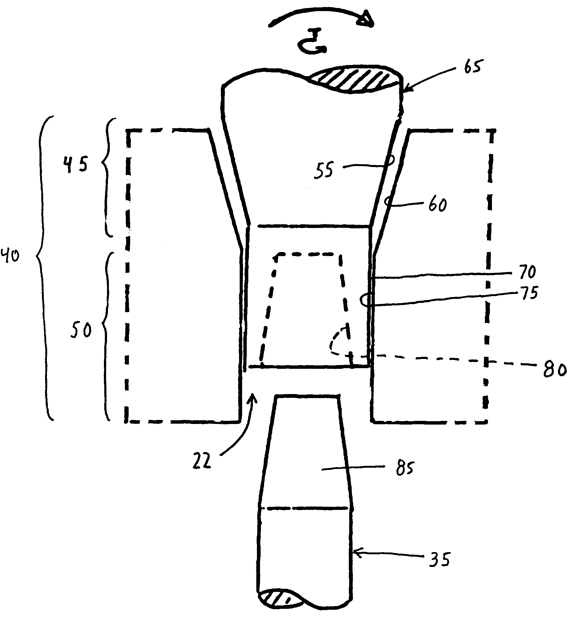
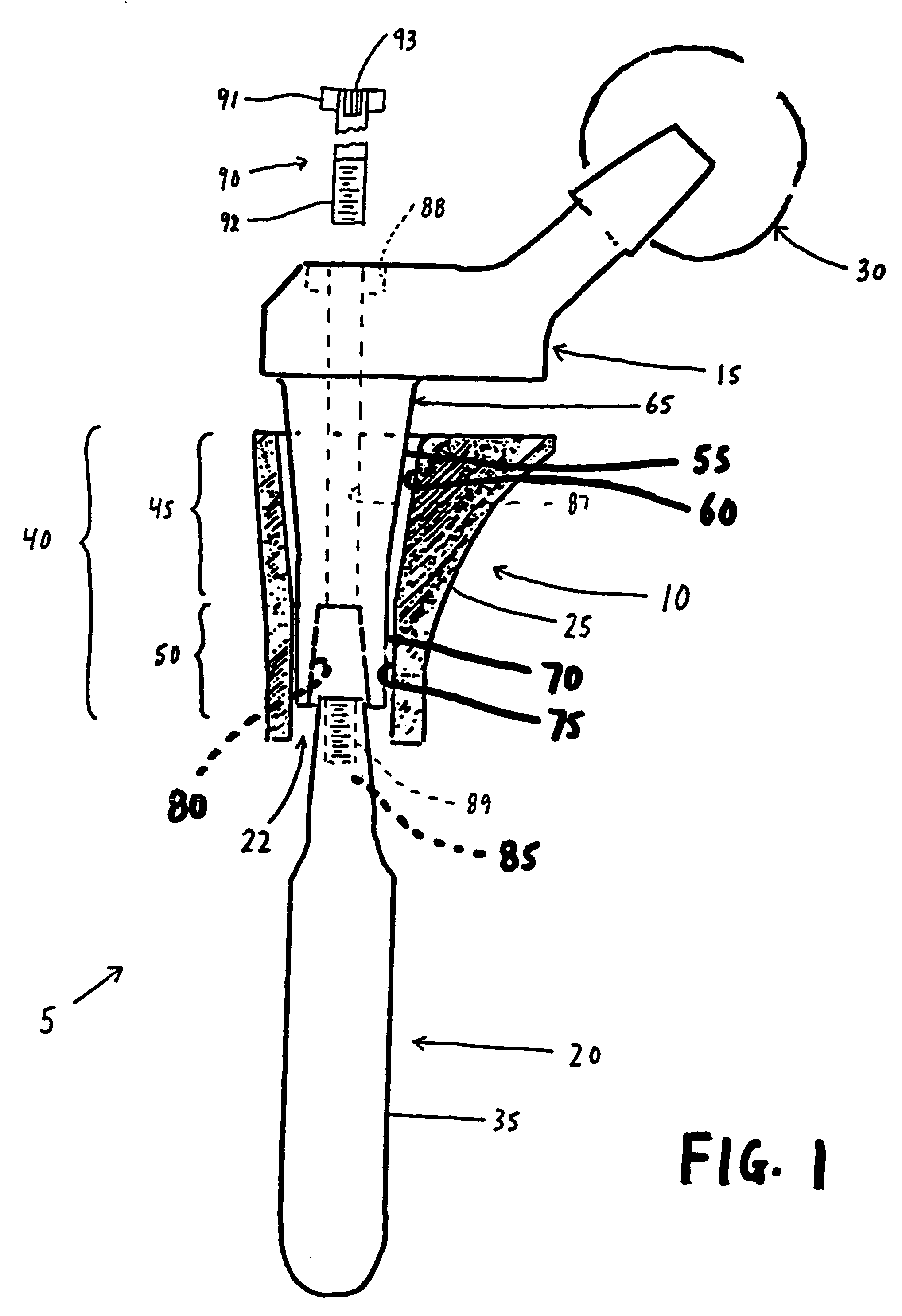
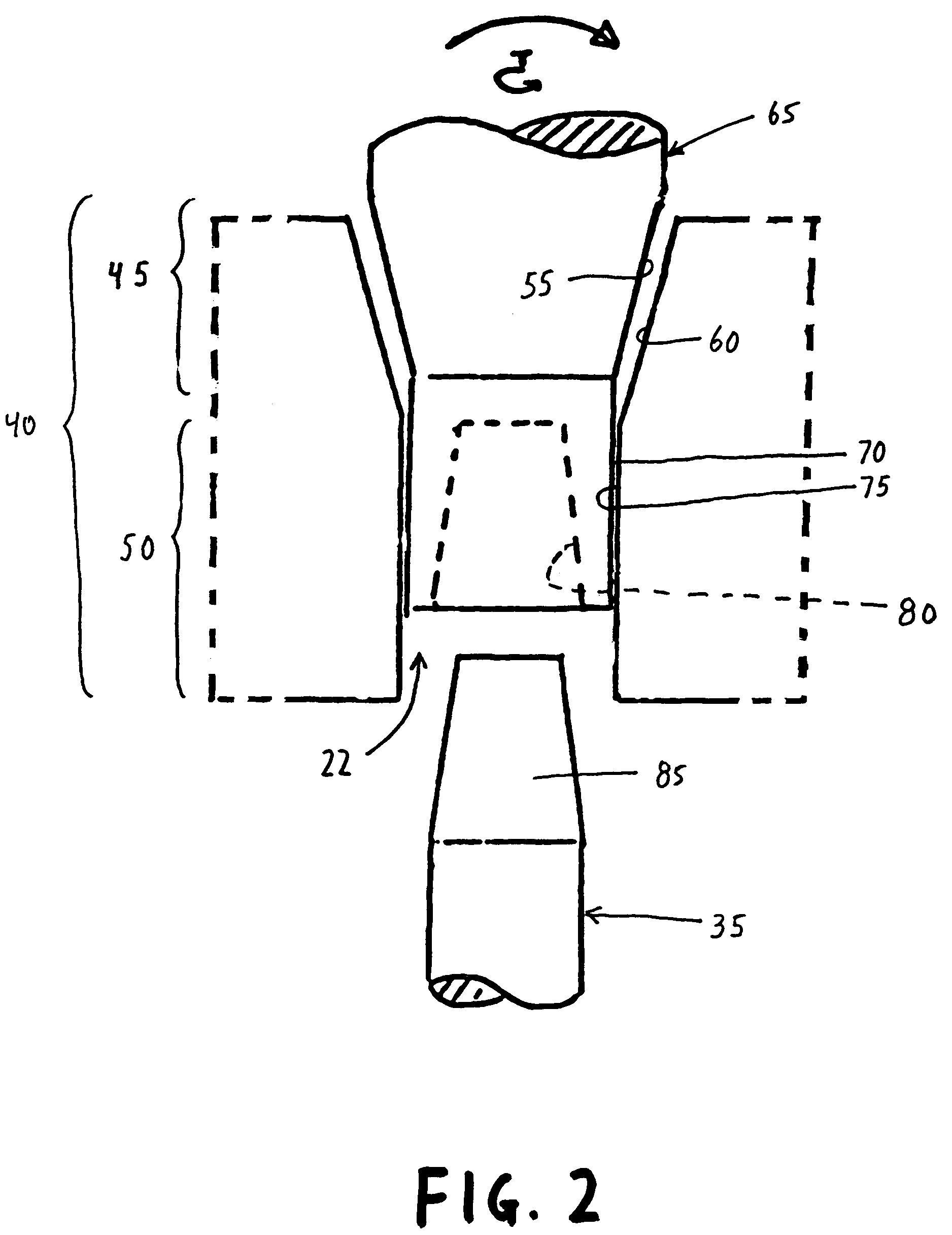
[0026]Looking first at FIG. 1, there is shown a prosthetic femoral stem component 5 formed in accordance with the present invention. Prosthetic femoral stem component 5 generally comprises a body element 10, a neck element 15 and a stem element 20. Body element 10 includes a central aperture 22 into which portions of neck element 15 and stem element 20 extend. Body element 10 is selected so that its outer surface 25 is properly sized to be seated in the proximal section of a resected femur. Neck element 15 is selected so that when it is mounted to the remainder of prosthetic femoral stem component 5 deployed within the femur, the neck element's ball 30 will be properly seated in the hip joint's corresponding acetabular cup. Stem 20 is selected so that its outer surface 35 is properly sized to be seated within the medullary canal of the femur.

[0027]In accordance with the present invention, body element 10, neck element 15 and stem element 20 are adapted to be secured to one another u...


PUM


Abstract

A prosthetic femoral stem component comprising a body element, a neck element and a stem element, with the body element, neck element and stem element being secured to one another with a modular connection, wherein the modular connection comprises a taper junction and an engaged-fit junction.

Description

REFERENCE TO PENDING PRIOR PATENT APPLICATIONS[0001]This is a continuation of prior U.S. patent application Ser. No. 09 / 909,923, filed Jul. 20, 2001 now U.S. Pat. No. 6,682,568, by Alfred S. Despres III et al. for MODULAR FEMORAL STEM COMPONENT FOR A HIP JOINT PROSTHESIS which in turn claims benefit of (1) prior U.S. Provisional Patent Application Ser. No. 60 / 219,955, filed Jul. 20, 2000 by Alfred S. Despres III et al. for MODULAR ORTHOPEDIC CONNECTION; and (2) prior U.S. Provisional Patent Application Ser. No. 60 / 219,963, filed Jul. 20, 2000 by Alfred S. Despres III et al. for FORCE COUPLE CONNECTION. The three above-identified patent applications are hereby incorporated herein by referenceFIELD OF THE INVENTION[0002]This invention relates to surgical apparatus and procedures in general, and more particularly to orthopedic prostheses for restoring the hip joint.BACKGROUND OF THE INVENTION[0003]Joint replacement surgery seeks to replace portions of a joint with prosthetic components...

Claims


Application Information

Patent Timeline
Patent Type & Authority Patents(United States)
IPC IPC(8): A61F2/32A61B17/56A61F2/00A61F2/30A61F2/34A61F2/36A61F2/38A61F2/46
CPCA61F2/30734A61F2/36A61F2/389Y10T403/4966A61F2/34A61F2/3662A61F2/367A61F2/3676A61F2002/30092A61F2002/30143A61F2002/30332A61F2002/3035A61F2002/30354A61F2002/30405A61F2002/30434A61F2002/30484A61F2002/30495A61F2002/30512A61F2002/30604A61F2002/30736A61F2002/30738A61F2002/30772A61F2002/30795A61F2002/30797A61F2002/30808A61F2002/30886A61F2002/3611A61F2002/3625A61F2002/365A61F2002/3652A61F2002/3674A61F2002/3694A61F2002/4638A61F2210/0014A61F2220/0025A61F2220/0033A61F2220/0041A61F2230/0017Y10T403/7064Y10T403/635Y10T403/7039Y10T403/55Y10T403/557Y10T403/4949Y10T403/4941Y10T403/4924Y10T403/4958A61F2/32F16B2200/10A61F2002/30507A61F2002/30433
Inventor DESPRES, III, ALFRED S.HAYES, JR., DANIEL E. E.
Owner DEPUY PROD INC
Learn More