Modular prosthetic component with improved body shape

a technology of prosthesis and body shape, applied in the field of surgical equipment and procedures, can solve the problems of difficulty in providing the correct prosthesis femoral stem component for patients, the distal section of the prosthesis may not be appropriately sized for proper seating in the distal section of the femur, and achieve the effect of restoring the hip join

Inactive Publication Date: 2005-12-22
SHALBY ADVANCED TECH INC
View PDF18 Cites 47 Cited by
  • Summary
  • Abstract
  • Description
  • Claims
  • Application Information

AI Technical Summary

Benefits of technology

[0019] Accordingly, one object of the present invention is to provide an improved configuration for the body element of a modular prosthetic femoral stem component.
[0022] Still another object of the present invention is to provide an improved method for restoring a hip joint.

Problems solved by technology

However, despite this, it has been found that it can be difficult to provide the correct prosthetic femoral stem component for patients.
This is due to the wide variation in patient anatomies and the practical limitations of hospital inventory.
By way of example, where a femoral component is selected having a proximal section appropriately sized for the proximal section of the resected femur, the distal section of the prosthesis may not be appropriately sized for proper seating in the distal section of the femur.
This can present serious problems for the patient, including problems relating to joint stability and pain.
If a prosthesis bypasses this region in favor of loading the more central section of the bone, resorbtion at the end of the bone will result.
This can eventually lead to fracture of the bone or loosening of the prosthesis.

Method used


Image

  • Modular prosthetic component with improved body shape
  • Modular prosthetic component with improved body shape
  • Modular prosthetic component with improved body shape

Examples


Embodiment Construction

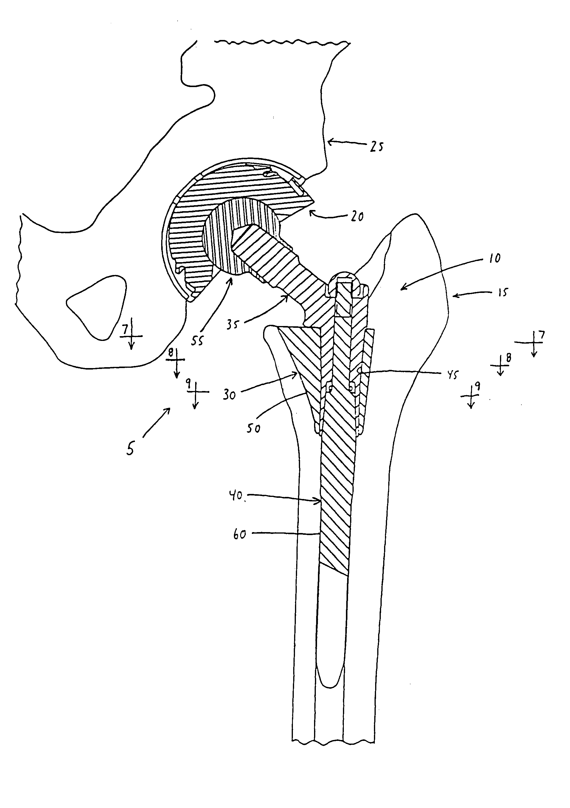
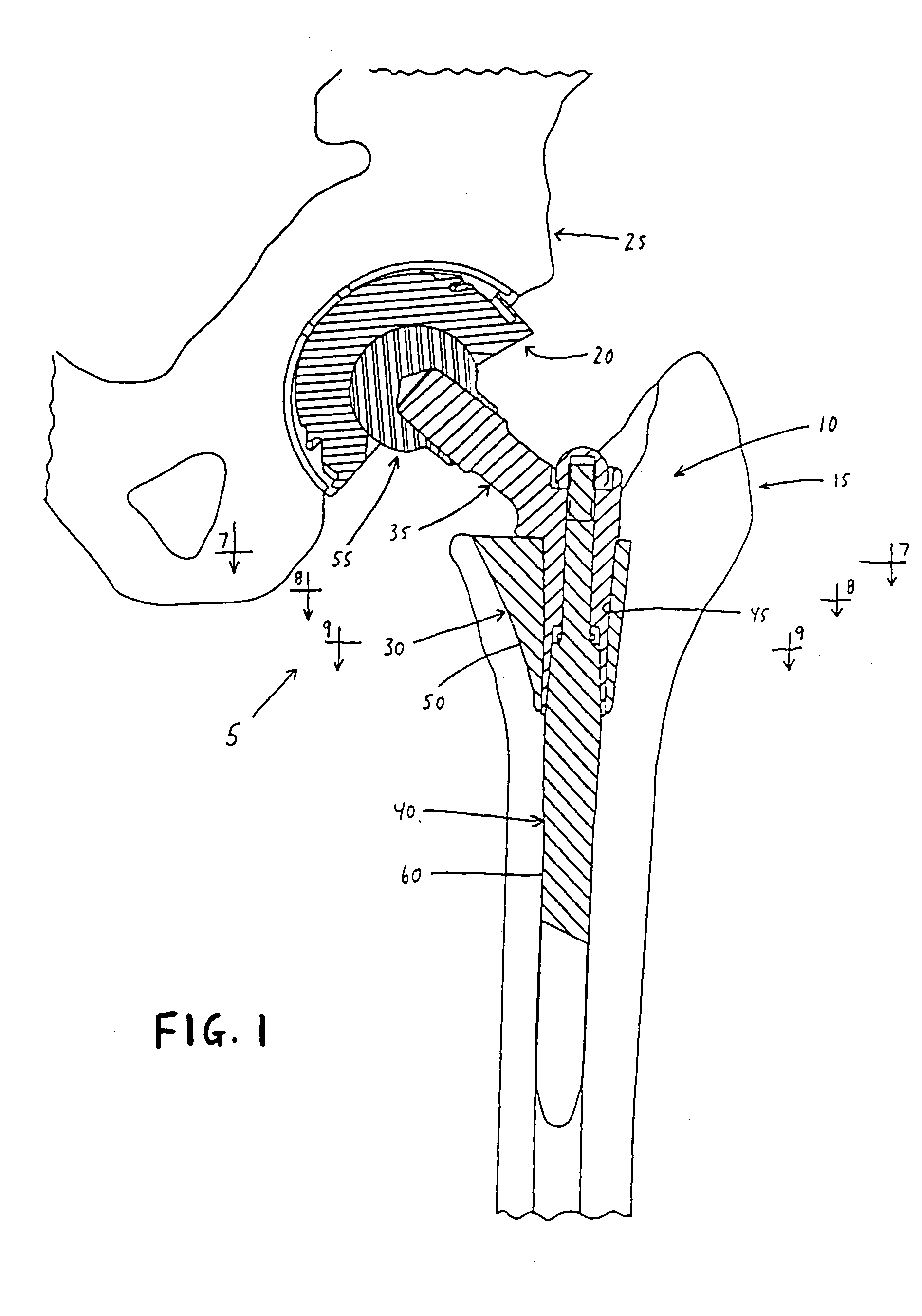
[0043] Looking first at FIG. 1, there is shown a prosthetic total hip joint 5 formed in accordance with the present invention. Prosthetic total hip joint 5 generally comprises a modular prosthetic femoral stem component 10 for seating in the proximal section of a resected femur 15, and a prosthetic acetabular cup component 20 for seating in the socket of the acetabulum 25.

[0044] Modular prosthetic femoral stem component 10 is formed in accordance with the present invention. Modular prosthetic femoral stem component 10 generally comprises a body element 30, a neck element 35 and a stem element 40. Body element 30 includes a central aperture 45 into which portions of neck element 35 and stem element 40 extend. As will hereinafter be discussed in further detail, body element 30 is configured and selected so that its outer surface 50 is appropriately sized for proper seating in the proximal section of resected femur 15. Neck element 35 is selected so that when it is mounted to the rema...


PUM


Abstract

An improved body element for use in a modular prosthetic stem component of the sort comprising a body element and at least one other element, wherein the body element and the at least one other element are joined together by at least one modular connection, wherein the improved body element comprises an anterior wall and a posterior wall, at least one of the anterior wall and the posterior wall converging toward the other on the medial side of the body element and diverging away from the other on the lateral side of the body element, whereby the body element approximates a general wedge shape.

Description

REFERENCE TO PENDING PRIOR PATENT APPLICATION [0001] This patent application claims benefit of pending prior U.S. Provisional Patent Application Ser. No. 60 / 233,875, filed Sep. 20, 2000 by Daniel E. E. Hayes, Jr. et al. for MODULAR PROSTHETIC IMPLANT (Attorney's Docket No. HAYES-5 PROV), which patent application is hereby incorporated herein by reference.FIELD OF THE INVENTION [0002] This invention relates to surgical apparatus and procedures in general, and more particularly to orthopedic prostheses for restoring a joint. BACKGROUND OF THE INVENTION [0003] Joint replacement surgery seeks to replace portions of a joint with prosthetic components so as to provide long-lasting function and pain-free mobility. [0004] For example, in the case of a prosthetic total hip joint, the head of the femur is replaced with a prosthetic femoral stem component, and the socket of the acetebulum is replaced by a prosthetic acetabular cup component, whereby to provide a prosthetic total hip joint. [00...

Claims


Application Information

Patent Timeline
Patent Type & Authority Applications(United States)
IPC IPC(8): A61F2/00A61F2/30A61F2/32A61F2/34A61F2/36
CPCA61F2/30734A61F2230/0026A61F2/32A61F2/34A61F2/36A61F2/3662A61F2/367A61F2002/30112A61F2002/30156A61F2002/30158A61F2002/30332A61F2002/30354A61F2002/30405A61F2002/30512A61F2002/30604A61F2002/30736A61F2002/30738A61F2002/30827A61F2002/30886A61F2002/3611A61F2002/3625A61F2002/365A61F2002/3652A61F2002/3674A61F2002/3694A61F2220/0025A61F2220/0033A61F2230/0004A61F2230/0023A61F2/30771A61F2002/30507
Inventor HAYES, DANIEL E. E. JR.DESPRES, ALFRED S. III
Owner SHALBY ADVANCED TECH INC
Why Eureka
Try Eureka