Electrolyzer pressure equalization system

Inactive Publication Date: 2006-08-29
UNIV OF MASSACHUSETTS
View PDF31 Cites 31 Cited by
  • Summary
  • Abstract
  • Description
  • Claims
  • Application Information

AI Technical Summary

Benefits of technology

[0005]This invention relates to a regenerative electrolyzer/fuel cell system including an energy storage system. The storage system can hold at a relatively high pres

Problems solved by technology

While the use of petroleum-based resources to generate electrical power is a possibility, petroleum-based resources have environmental issues, concerns as non-renewable resources, and the logistics of getting the petroleum-based resources from the source to the area of need.
However, these renewable energy technologies generally need a storage mechanism to store energy in that they ar

Method used


Image

  • Electrolyzer pressure equalization system
  • Electrolyzer pressure equalization system
  • Electrolyzer pressure equalization system

Examples


Embodiment Construction

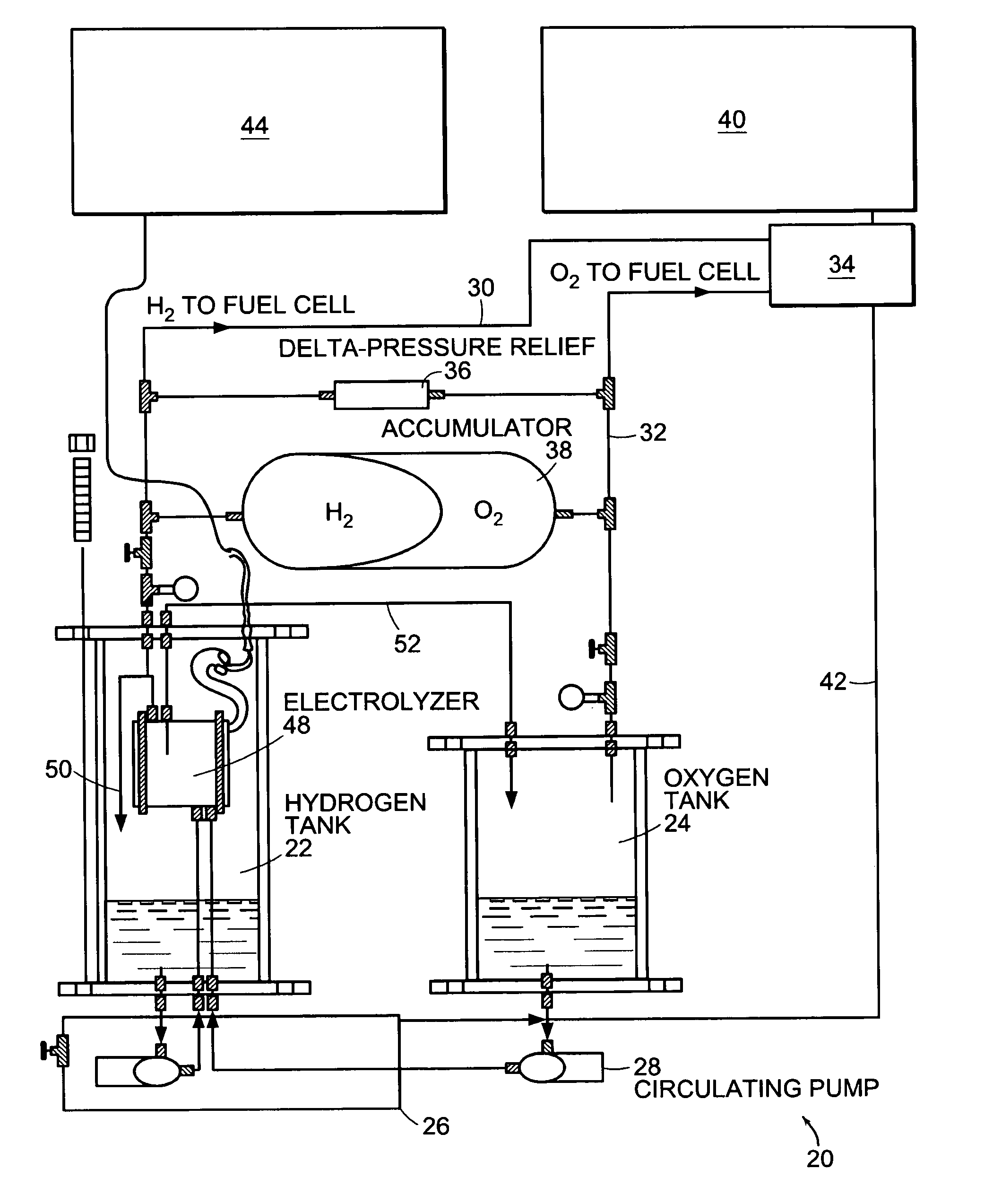
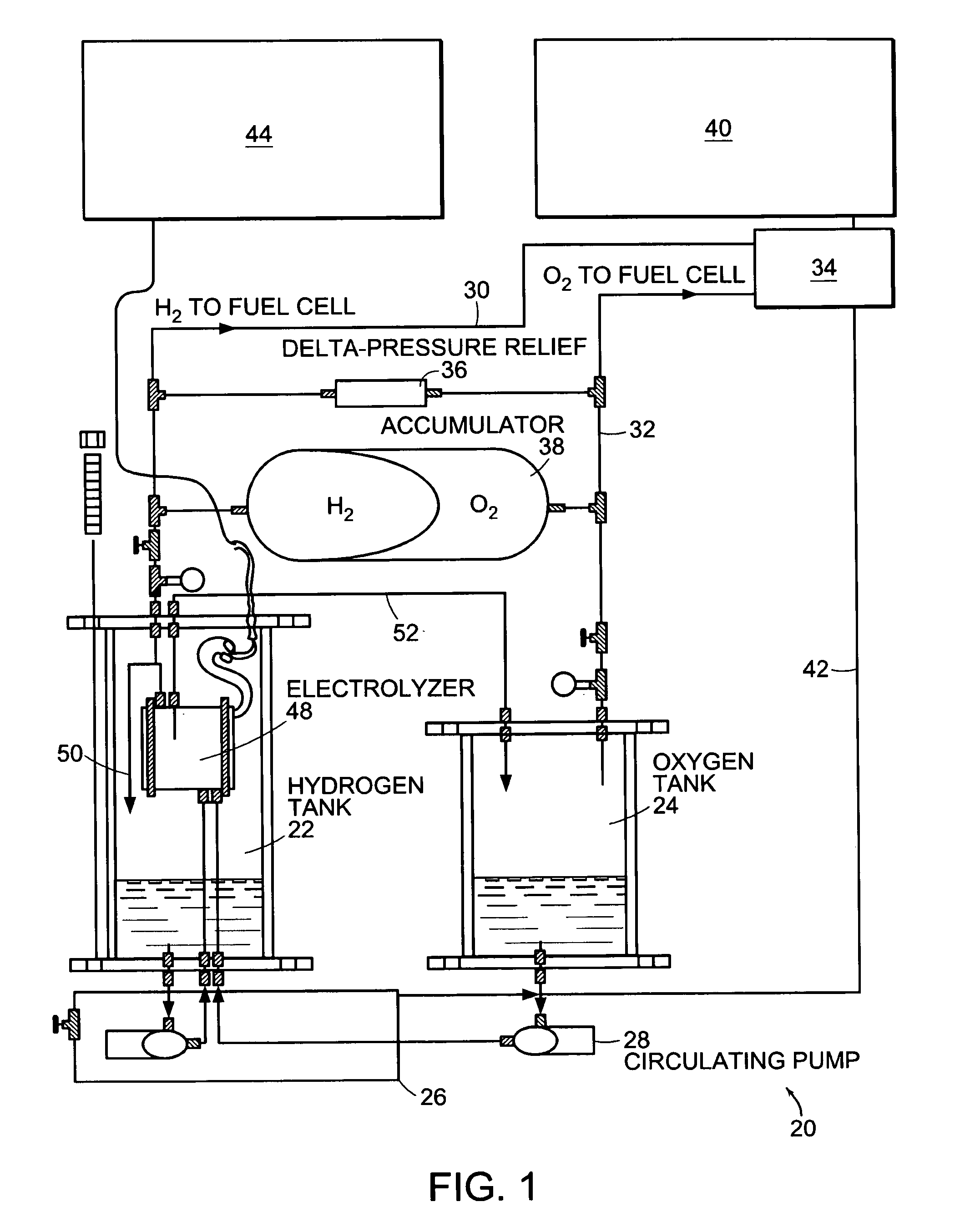
[0032]Referring to FIG. 1, a regenerative electrolyzer / fuel cell system according to the invention is generally shown as 20. The system 20 has a first pressurized storage tank 22 for holding hydrogen gas, a second pressurized storage tank 24 containing oxygen gas. The first pressurized tank 22 and the second pressurized tank 24 in addition contain water. A water line 26 extends between the two pressurized tanks 22 and 24. A circulating pump 28 in an embodiment helps control the relative water levels.

[0033]The regenerative electrolyzer / fuel cell 20 has a pair of output lines 30 and 32 for carrying hydrogen gas and oxygen gas respectively to a fuel cell 34. Interposed between the output line 30 for the hydrogen gas and the output line 32 for the oxygen gas is a differential pressure relief valve 36 for maintaining the pressure within the hydrogen system and the oxygen system in close relationship. In addition, an accumulator 38 is interposed between the output line 30 for the hydrogen...


PUM

PropertyMeasurementUnit
Pressureaaaaaaaaaa
Pressureaaaaaaaaaa
Pressureaaaaaaaaaa

Abstract

An energy storage system has a first pressurized tank for carrying water and hydrogen gas and a second pressurized tank for carrying water and oxygen gas. A first output line connects to the pressurized tank for carrying hydrogen gas from the tank. A second output line connects to the second pressurized tank for carrying oxygen gas from the second tank. The energy storage system has a differential-pressure relief valve connected to the output lines to maintain the gases within a defined pressure differential. A water line connects to both pressurized tanks for maintaining relative water levels in the tanks. An electrolyzer is maintained under pressure and receives water from at least one of the pressurized tanks and creates hydrogen gas and oxygen gas for storage in the pressurized tanks. An accumulator connects to the output lines and having a movable diaphragm that separates the gases and moves to adjust volume to equalize pressure. A regeneration system having the energy storage system and a fuel cell for generating electrical energy is connected to the output lines. A catalyst hood overlies the electrolyzer. In a preferred embodiment of the regeneration system, both the electrolyzer and the fuel cell have a proton exchange membrane. A solar array is connected to the electrolyzer in the regeneration system.

Description

CROSS REFERENCES TO RELATED APPLICATIONS[0001]The present application claims the benefit of U.S. Provisional Application No. 60 / 374,732, filed Apr. 23, 2002. The entire contents of the above application are incorporated herein by reference in entirety.BACKGROUND OF THE INVENTION[0002]There are billions of people on the earth who live without access to reliable electricity. Even a modest amount of electrical power can tremendously improve the quality of life for people in under-served regions. Basic applications in these rural areas could include items such as lighting, medical, and health related items such as refrigeration for medicines and food.[0003]While the use of petroleum-based resources to generate electrical power is a possibility, petroleum-based resources have environmental issues, concerns as non-renewable resources, and the logistics of getting the petroleum-based resources from the source to the area of need. Renewable energy technologies including solar photovoltaic, ...

Claims


Application Information

Patent Timeline
IPC IPC(8): C25B9/20H01M8/06H01M8/18C25B1/08C25B1/12C25B15/00H01M8/04H01M8/10H01M16/00
CPCC25B1/12C25B15/00H01M8/04104H01M8/04201H01M16/003Y02E60/50H01M2008/1095Y02E60/366Y02E70/10Y02E70/20C25B1/04C25B9/05Y02E60/36Y02P20/133
Inventor DUFFY, JOHN J.SHAPIRO, DANIEL
Owner UNIV OF MASSACHUSETTS
Why Eureka
Try Eureka