Tamper proof container

a container and tamper-proof technology, applied in the field of tamper-proof containers, can solve the problems of optical path broken or altered, and the interior surface portion of the interior surface is also damaged,

Inactive Publication Date: 2006-08-29
3D FUSE TECH
View PDF45 Cites 34 Cited by
  • Summary
  • Abstract
  • Description
  • Claims
  • Application Information

AI Technical Summary

Benefits of technology

[0008]Embodiments of the present invention can detect a breach of the interior surface of a shipping container or box and can then trigger an alarm or notify a central location, such as a ship's control room or a port notification system. At least one liner sheet lines at least a portion of at least one interior surface of the shipping container or box, such that a breach of the portion of the interior surface also damages the liner sheet. The liner sheet defines an optical path extending across at least a portion of the sheet. The optical path is monitored for a change, such as a loss of continuity, in an optical characteristic of the optical path. If the container or box interior surface is breached, one or more portions of the optical path are affected and the optical path is broken or altered. The detected change in the optical path can be used to trigger an alarm, such as an annunciator. In addition, a message can be sent, such as by a wireless communication system, to a central location.

Problems solved by technology

At least one liner sheet lines at least a portion of at least one interior surface of the shipping container or box, such that a breach of the portion of the interior surface also damages the liner sheet.
If the container or box interior surface is breached, one or more portions of the optical path are affected and the optical path is broken or altered.

Method used


Image

  • Tamper proof container
  • Tamper proof container
  • Tamper proof container

Examples


Embodiment Construction

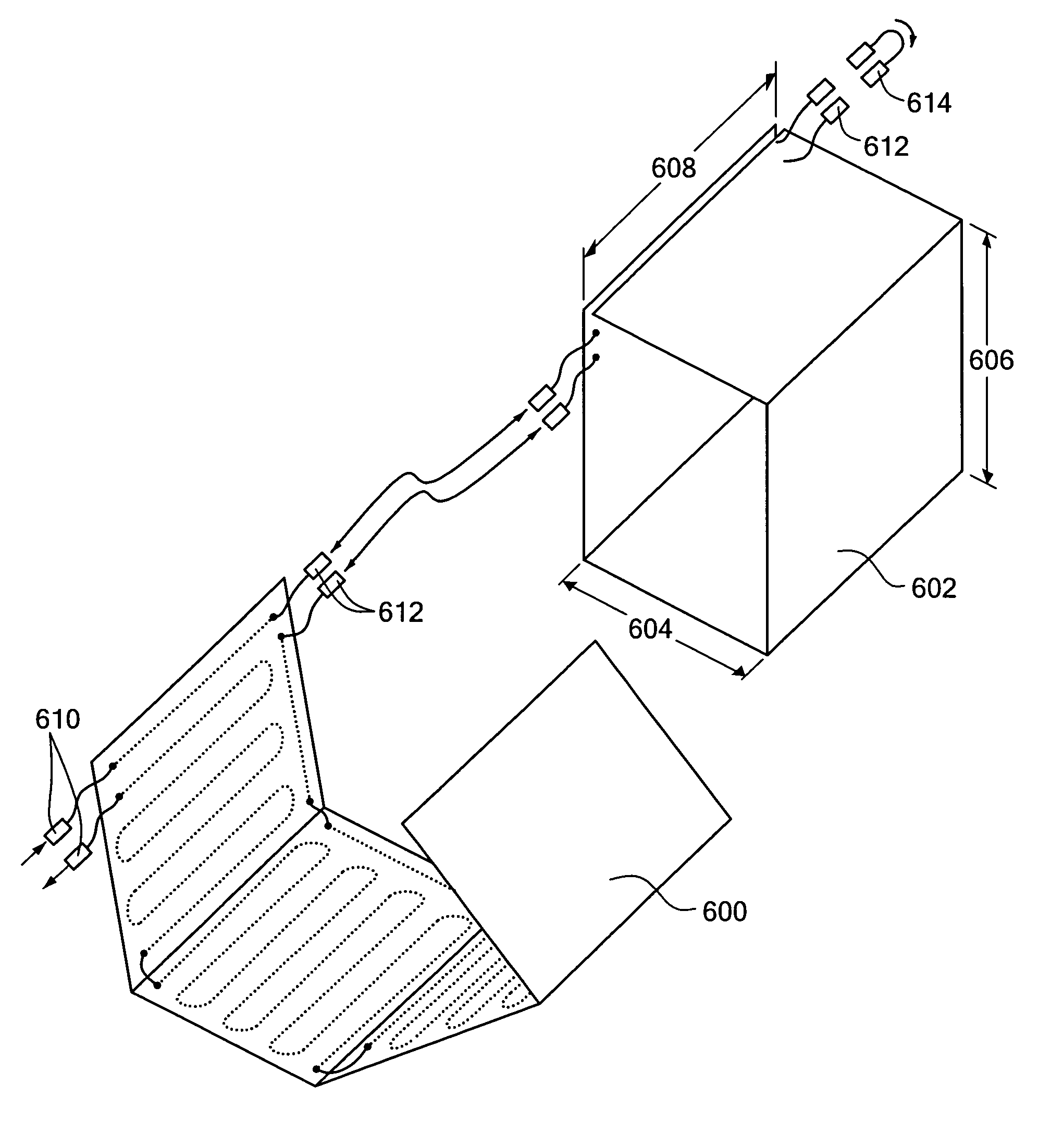
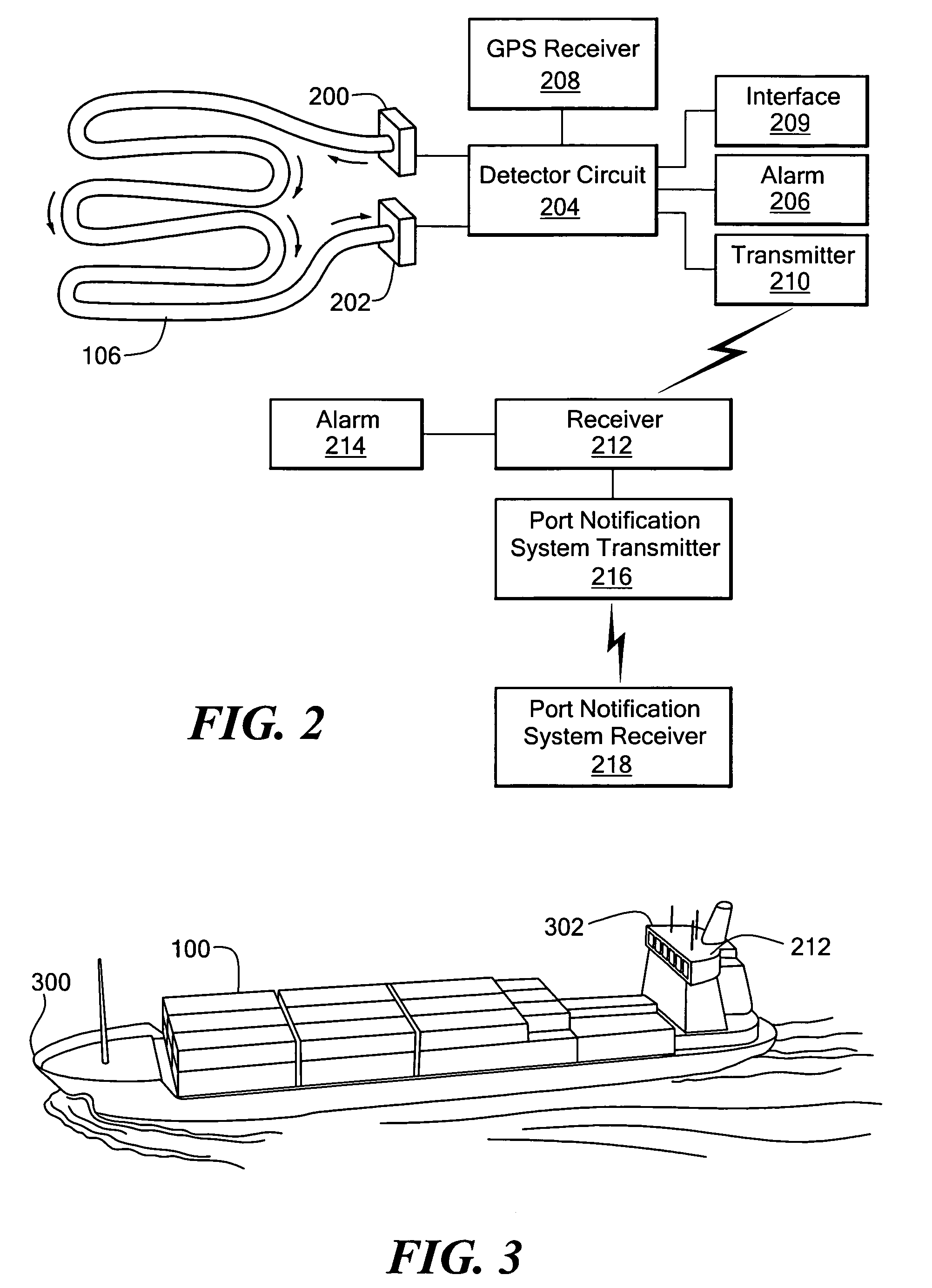
[0030]The present invention provides methods and apparatus to detect tampering with a six-sided or other type of container or box, as well as methods of manufacturing such apparatus. A preferred embodiment detects a breach in a monitored surface of a container or box. A liner sheet lines at least a portion of an interior surface of the container or box, such that a breach of the portion of the container interior surface damages the liner sheet. The liner sheet defines an optical path extending across at least a portion of the sheet. For example, an optical fiber can be woven into, or sandwiched between layers of, the liner sheet. The optical path is monitored for a change in an optical characteristic of the optical path. For example, a light source can illuminate one end of the optical fiber, and a light sensor can be used to detect the illumination, or a change therein, at the other end of the optical fiber. If the container or box surface is breached, one or more portions of the o...


PUM


Abstract

A liner sheet lines at least a portion of an interior surface of a shipping container or box and defines an optical path extending across at least a portion of the sheet, such that a breach of the interior surface also alters an optical characteristic of the optical path. For example, an optical fiber can be woven into, or sandwiched between layers of, the liner sheet. The optical path is monitored for a change in an optical characteristic. If the container or box interior surface is breached, one or more portions of the optical fiber are severed or otherwise damaged, and the optical path is altered. The detected change in the optical path can be used to trigger an alarm, such as an annunciator, or to send a message that includes information concerning the container's contents or time or location of the container when the breach occurred to a central location, such as a ship's control room or a port notification system.

Description

CROSS-REFERENCE TO RELATED APPLICATIONS[0001]This application claims the benefit of U.S. Provisional Application No. 60 / 535,449, titled “TAMPER PROOF CONTAINER,” filed Jan. 9, 2004, the contents of which are hereby incorporated by reference herein.STATEMENT REGARDING FEDERALLY SPONSORED RESEARCH OR DEVELOPMENT[0002](Not Applicable)BACKGROUND OF THE INVENTION[0003]1. Field of the Invention[0004]The present invention relates to security systems for shipping containers, boxes and the like and, more particularly, to such security systems that can detect tampering with, or breaches in, surfaces of such containers.[0005]2. Description of the Prior Art[0006]Cargo is often shipped in standardized containers, such as those used on trucks, trains, ships and aircraft. Smaller units of cargo are typically shipped in cardboard boxes and the like. It is often difficult or impossible to adequately guard these containers and boxes while they are in transit, such as on the high seas. In addition, so...

Claims


Application Information

Patent Timeline
Patent Type & Authority Patents(United States)
IPC IPC(8): G01J1/04G01J1/42G01J5/08G02B6/00G08B13/12
CPCG08B13/126
Inventor BEINHOCKER, GILBERT D.
Owner 3D FUSE TECH
Why Eureka
Try Eureka