Antenna unit

a technology for antennas and units, applied in the direction of antennas, antenna details, antenna adaptation in movable bodies, etc., can solve the problems of large size of the apparatus, limited installation space, and unsuitable mounting on aircraft, and achieve the effect of high accuracy and low cos

Inactive Publication Date: 2006-08-29
MITSUBISHI ELECTRIC CORP
View PDF10 Cites 46 Cited by
  • Summary
  • Abstract
  • Description
  • Claims
  • Application Information

AI Technical Summary

Benefits of technology

[0017]As a result, not only the phase amounts can be adjusted correspondingly to the two-channel polarized signals, but also the amplitudes (attenuation amounts) can be adjusted correspondingly to the two-channel polarized signals. Thus, even when a reflector antenna is used, the antenna apparatus can be inexpensively provided which can perform transmission / reception of a signal to / from a satellite at high accuracy, and is miniaturized to be suitable for mounting on an aircraft or the like.

Problems solved by technology

The conventional antenna apparatus shown in FIG. 8 uses the 180° polarizer 100 constructed of a waveguide, there is a problem that the size of the apparatus becomes large, and is not suitable for mounting on an aircraft or the like in which an installation space is limited.
However, since it is necessary that according to the required antenna performance, the many element antennas (array antennas) are arranged and the variable power divider corresponding to each of the element antennas is provided, although a highly efficient antenna apparatus can be obtained, there is a problem that it becomes expensive.

Method used


Image

  • Antenna unit
  • Antenna unit
  • Antenna unit

Examples


embodiment 1

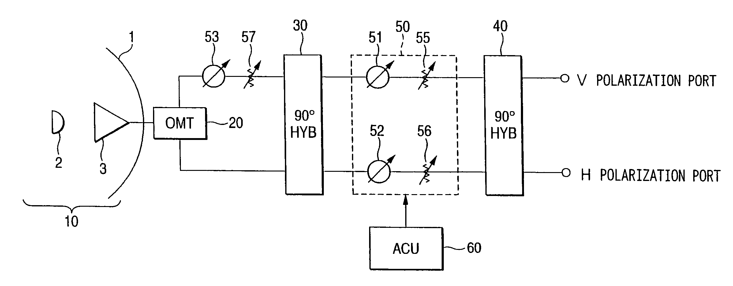
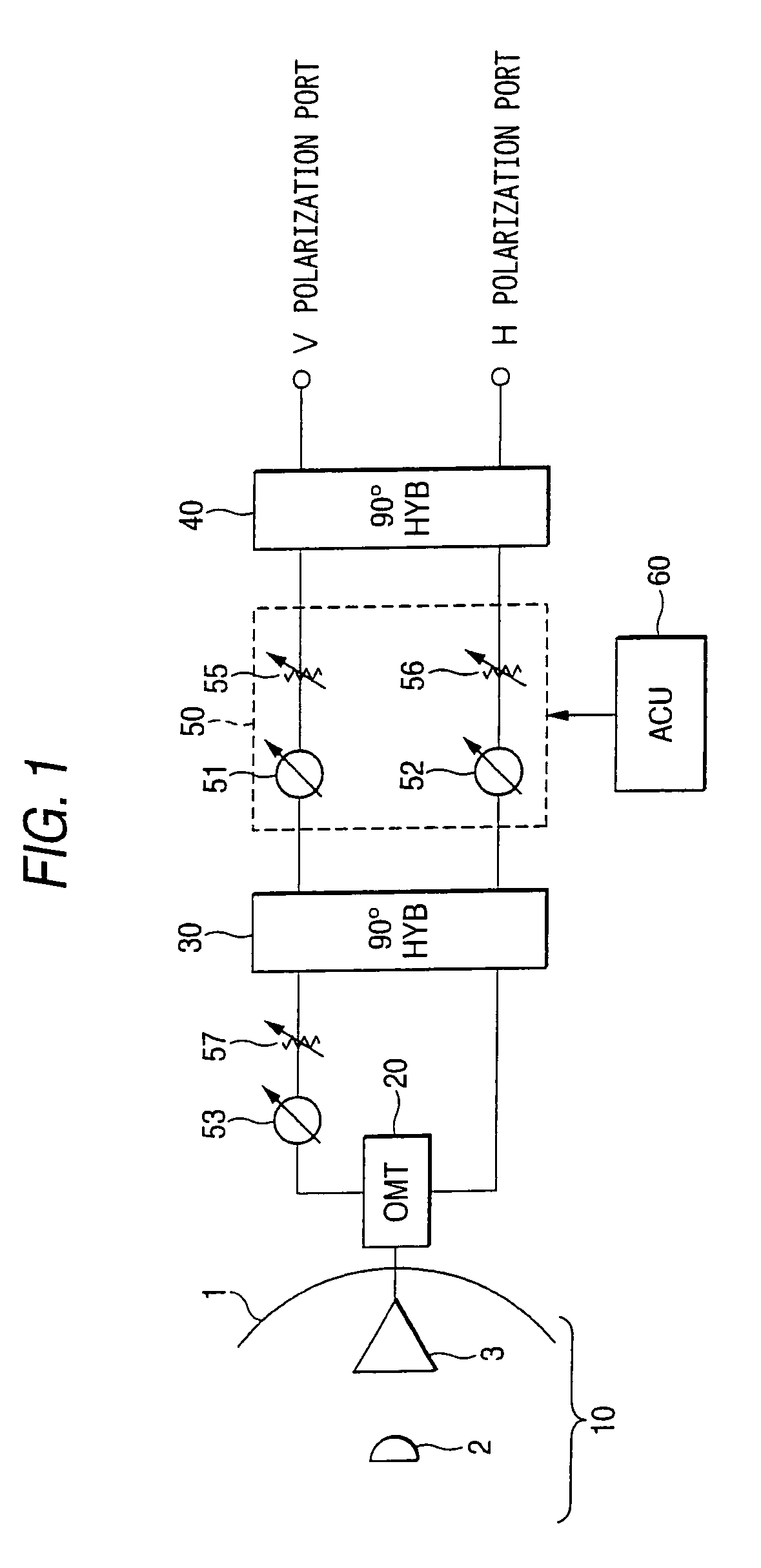
[0029]FIG. 1 is a view showing a structure of an antenna apparatus according to embodiment 1 of the invention.

[0030]In FIG. 1, reference numeral 10 denotes a reflector antenna part which receives a radio frequency signal (linear polarization signal) transmitted from a not-shown satellite or transmits a radio frequency signal (linear polarization signal) to the satellite, and the reflector antenna part 10 includes a spherical main reflector 1, a secondary reflector 2 and a horn antenna 3.

[0031]Reference numeral 20 denotes an orthomode transducer (OMT: ORTHO MODE TRANSDUCER) functioning as an interface between the antenna part 10 and a signal circuit, and the orthomode transducer 20 divides the radio frequency signal (linear polarization signal) received by the reflector antenna part 10 into two-channel orthogonal polarization, or combines two-channel orthogonal polarization to convert them into the linear polarization signal.

[0032]Reference numeral 30 denotes a first 90° phase combin...

embodiment 2

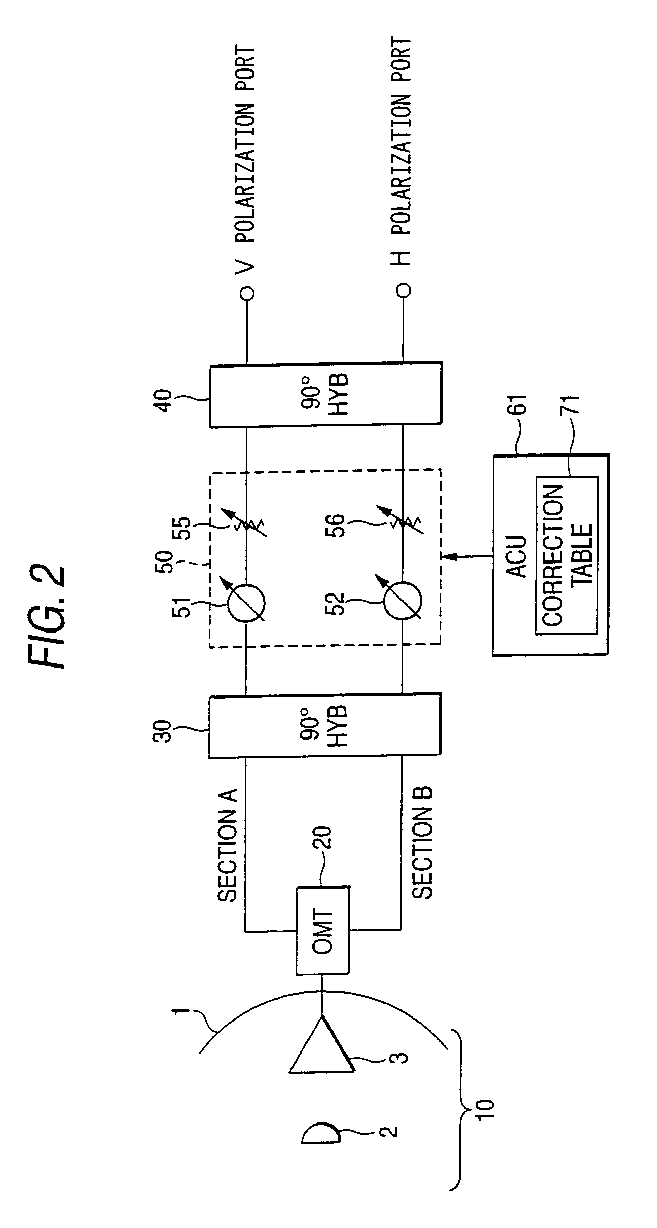
[0058]FIG. 2 is a view showing a structure of an antenna apparatus according to embodiment 2 of the invention.

[0059]As described above, an amplitude difference and a phase difference occurring in two-channel signal lines (indicated by a section A and a section B) between an orthomode transducer 20 and a first 90° phase combiner 30 become polarization plane setting errors.

[0060]Thus, in the antenna apparatus according to this embodiment, the amplitude difference and the phase difference occurring in the two-channel signal lines (the section A and the section B) between the orthomode transducer 20 and the first 90° phase combiner 30 are previously measured, and the measured values are stored as a correction table 71 in an antenna control unit 61.

[0061]When the control of variable phase shifters and variable attenuators in a phase-amplitude adjustment block 50 is performed by the antenna control unit 61, reference is made to the values stored in the correction table 71 and the control ...

embodiment 3

[0064]FIG. 3 is a view showing a structure of an antenna apparatus according to embodiment 3 of the invention.

[0065]In the case where an antenna apparatus is mounted on an aircraft, it is necessary that a polarization plane angle is calculated according to the position and tilt of the aircraft, and an antenna polarization plane angle of a reflector antenna part 10 is set.

[0066]An IRU (Inertia Reference Unit) 80 is mounted in an aircraft, and although the information of the position and tilt of the aircraft on which an antenna apparatus is mounted can be acquired from the IRU 80, a delay of several hundred msec occurs in data which can be acquired.

[0067]Thus, in the antenna apparatus according to this embodiment, a three-axis gyro 72 which can quickly acquire data of the position and tilt of the aircraft, although its accuracy is a little low, is mounted in an antenna control unit 62.

[0068]The antenna control unit 62 calculates a necessary polarization plane angle by using the data o...


PUM


Abstract

In a variable power divider including a first 90° phase combiner (30), a second 90° phase combiner (40), and a phase-amplitude adjustment block (50), the phase-amplitude adjustment block (50) includes, correspondingly to two-channel polarized signals, variable phase shifters (51, 52) for adjusting their phase amounts and variable attenuators (55, 56) for adjusting amplitudes (attenuation amounts), and the phase amounts and the amplitudes of the two-channel polarized signals can be adjusted by an antenna control unit (60). Further, there are included a phase shifter (53) and an attenuator (57) provided on two-channel signal lines between an orthomode transducer (20) and a first 90° phase combiner (30) and for equalizing the amplitudes and phases of the two-channel polarized signals. By this, an antenna apparatus can be inexpensively provided which uses a reflector antenna (10) to perform transmission / reception of a signal to / from a satellite at high accuracy, and is miniaturized to be suitable for mounting on an aircraft or the like.

Description

[0001]This application is a 371 of PCT / JP03113913 filed Oct. 30, 2003.TECHNICAL FIELD[0002]The present invention relates to an antenna apparatus for transmitting / receiving a modulating signal of a radio frequency to / from a satellite, and particularly to a structure of an antenna apparatus which uses a reflector antenna and is miniaturized to be suitable for mounting on a moving body such as an aircraft.BACKGROUND ART[0003]FIG. 8 is a view showing a structure of a conventional antenna apparatus using a reflector antenna. In the drawing, reference numeral 10 denotes a reflector antenna part, and the reflector antenna part 10 includes a spherical main reflector 1, a secondary reflector 2, and a horn antenna 3.[0004]Reference numeral 100 denotes a substantially cylindrical 180° polarizer, and the 180° polarizer 100 is rotatably supported by a rotary joint 110. The 180° polarizer 100 is rotated to coincide with a polarization coming from a satellite (not shown) or a polarization transmit...

Claims


Application Information

Patent Timeline
Patent Type & Authority Patents(United States)
IPC IPC(8): H01Q13/00H01P5/04H01Q3/26H01Q13/02H01Q19/13H01Q19/19H01Q21/24
CPCH01Q3/26H01Q13/0258H01Q19/13H01Q21/24H01P1/161H01Q19/19H01P1/18
Inventor SHIMAWAKI, YUTAKATAKEUCHI, NORIONAITOU, IZURUYOSHIZAWA, HIDENORI
Owner MITSUBISHI ELECTRIC CORP
Why Eureka
Try Eureka