Position-detecting device

Inactive Publication Date: 2005-02-03
SONY CORP
View PDF3 Cites 27 Cited by
  • Summary
  • Abstract
  • Description
  • Claims
  • Application Information

AI Technical Summary

Benefits of technology

To solve these problems the present invention has been developed, and it is an object

Problems solved by technology

However, such a resistor type touch panel has poor durability.
Further, since the resistor type touch panel is superposed on a display, a quality of an image on the display is deteriorated, and furthermore, it is difficult to miniaturize the device because it becomes thick.
Such an optical touch panel, however, is expensive because ver

Method used


Image

  • Position-detecting device
  • Position-detecting device
  • Position-detecting device

Examples


first embodiment

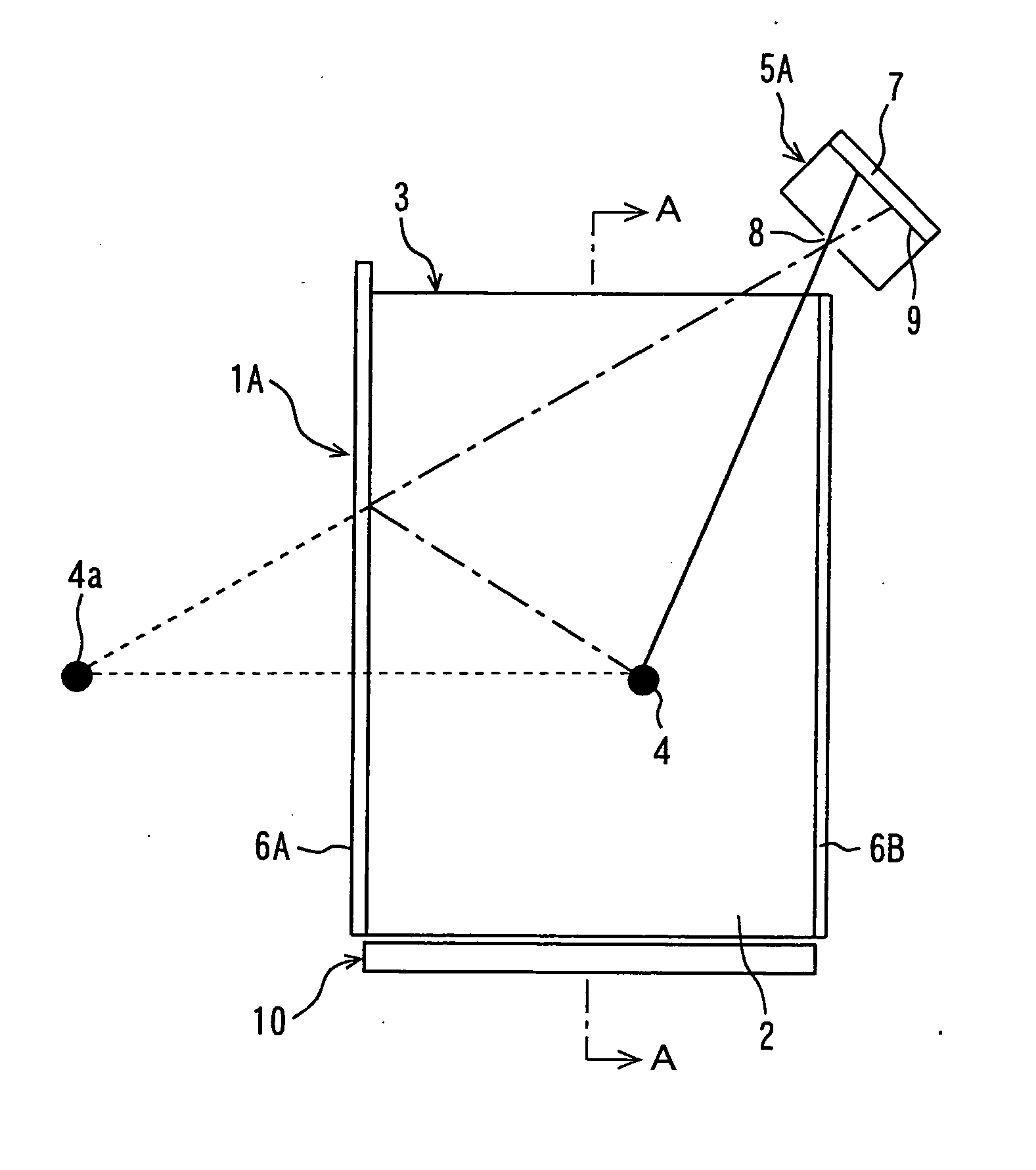
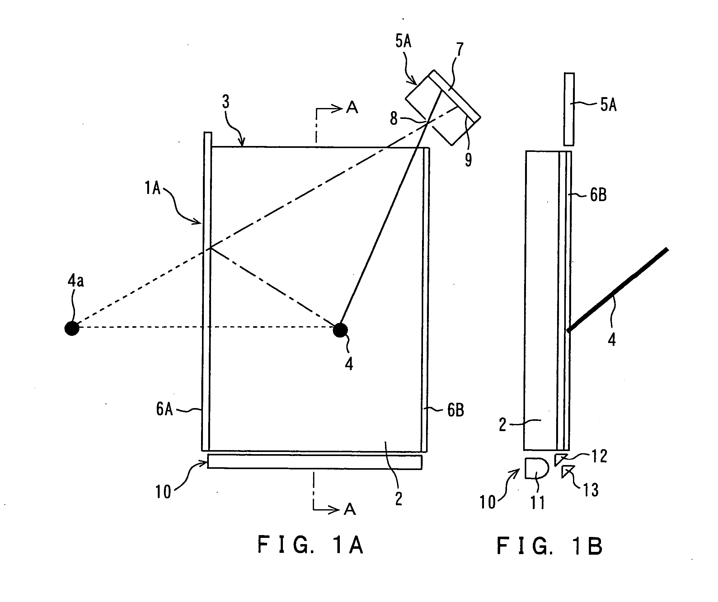
The following will describe embodiments of the present invention with reference to drawings. FIGS. 1A and 1B are explanatory diagrams for showing a configuration of a position-detecting device according to the invention. FIG. 1A is a plan view thereof and FIG. 1B is a cross-sectional view thereof taken along line A-A of FIG. 1A. It is to be noted that hatching for indicating a cross-sectional view is not carried out to prevent the drawings from becoming too complicated.

The first embodiment of the position-detecting device 1A according to the invention is used to obtain a two-dimensional position of a detection target and utilized as, for example, a touch panel device. In the position-detecting device 1A, a planate detection range 3 is organized on a front face of a screen of a liquid crystal display 2, which is one example of a display. To obtain a position pointed by a fescue 4, which is one example of the detection target, in this detection range 3, a camera unit 5A and mirrors 6...


PUM


Abstract

A liquid crystal display is provided with a detection range on its screen. Along right and left sides of this detection range, two mirrors are arranged as opposed to each other, and along one of sides perpendicular to the sides along which the mirrors are arranged a camera unit is arranged. The camera unit comprises a linear light sensor and a pinhole. When an arbitrary position in the detection range is pointed by a fescue, the linear light sensor detects a real image of a detection target. The linear light sensor also detects a mapped image of the detection target reflected by the mirror. Then, positional information of the real image and the mapped image of the detection target on the linear light sensor is used to obtain a two-dimensional position of the fescue in the detection range.

Description

BACKGROUND OF THE INVENTION 1. Field of the Invention The present invention relates to a position-detecting device for detecting a position of a detection target. More specifically, it relates to a position-detecting device such as a touch panel. 2. Description of Related Art The position-detecting device such as a touch panel for obtaining two-dimensional coordinates of the position touched by a finger, pen, etc. has conventionally been proposed, in order to accomplish processing due to the touched position on a screen of a display with the finger, pen or the like. As the position-detecting device, a resistor type touch panel is widely used which employs a transparent sheet on which electrodes are arrayed in a lattice to obtain coordinates of a touched location from its change in their resistance value. However, such a resistor type touch panel has poor durability. Further, since the resistor type touch panel is superposed on a display, a quality of an image on the display is ...

Claims


Application Information

Patent Timeline
IPC IPC(8): G06F3/042G06F3/03G06F3/033G06F3/041G06K11/06G06M7/00H01L31/00
CPCG06F3/0428
Inventor OGAWARA, YOSHIAKITAKAKUWA, HIDEMI
Owner SONY CORP
Why Eureka
Try Eureka