
Method and apparatus for image forming capable of reducing mechanical stresses to developers during transportation for development

a technology of mechanical stress and development, applied in the field of method and apparatus for image forming, can solve the problems of large mechanical stress on the toner in the development unit, reduced flowability of toner, and accumulation of toner, so as to reduce the amount of charge with time, ensure long-term image quality, and reduce the effect of mechanical stress acting on the developer

Inactive Publication Date: 2006-08-29
RICOH KK
View PDF50 Cites 13 Cited by
  • Summary
  • Abstract
  • Description
  • Claims
  • Application Information

AI Technical Summary

Benefits of technology

The present invention provides an image forming method and apparatus that reduces mechanical stress on toner during development, allowing for high-quality development for a long period of time. This is achieved by forming a thin layer of developer on a developer carrying member using an electric field generated between the developer carrying member and the developer conveyance member. The thin layer of developer is then conveyed to the latent image carrying member for image development. The method and apparatus also include a protective layer, a powder pump, a recovery unit, a developer charge amount changing unit, an electrically conductive member, a toner, a process cartridge, and a detachable process cartridge. The technical effects of the invention include reducing mechanical stress on toner, preventing external additive burying into the developer, and ensuring long-term image quality.

Problems solved by technology

However, the toner in the development unit is subject to a large mechanical stress when the toner is formed into a thin layer by the thin layer forming member such as a thin layer forming blade or the developer limiting roller.
This reduces the flowability of the toner, thereby causing the toner to aggregate.
The aggregated toner reduces the amount charge thereof, thereby leading to scumming, and toner supply failure.
The toner tends to age rapidly, and maintaining image quality becomes difficult.

Method used


Image

  • Method and apparatus for image forming capable of reducing mechanical stresses to developers during transportation for development
  • Method and apparatus for image forming capable of reducing mechanical stresses to developers during transportation for development
  • Method and apparatus for image forming capable of reducing mechanical stresses to developers during transportation for development

Examples


first preferred embodiment

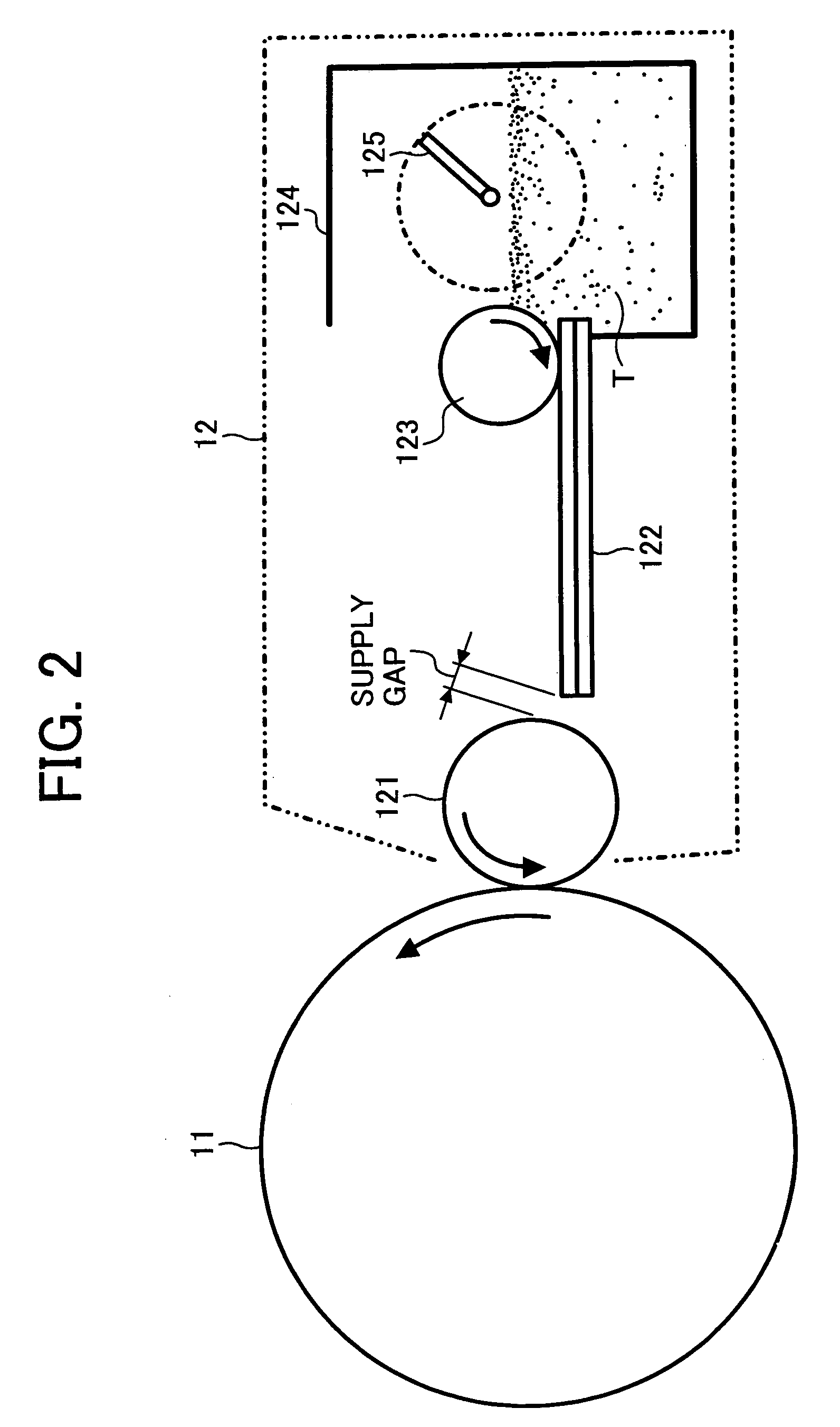
[0053]As shown in FIG. 2, the development unit 12 includes a hopper 124, a development roller 121, an electrostatic conveyance member 122, a supply roller 123, etc. The hopper 124 is filled with a toner T. The hopper 124 includes an agitator 125 which agitates the toner while moving the toner T to the supply roller 123. One end of the electrostatic conveyance member 122 extends into the hopper 124. The supply roller 123 is arranged to be in contact with the top surface of the electrostatic conveyance member 122 close to the one end thereof. With the supply roller 123 rotating, the toner T is supplied to the electrostatic conveyance member 122. The toner T is then conveyed toward the development roller 121 based on the mechanism of electrostatic conveyance, and is then supplied to the development roller 121 from the opposite end of the electrostatic conveyance member 122. The toner T is triboelectrically charged (to a negative charge in the first preferred embodiment) when being conv...

second preferred embodiment

[0075]A second embodiment is discussed below. The second embodiment performs a non-contact development process in which the development roller 121 faces the photoconductive drum 11 with a spacing maintained therebetween. The spacing therebetween is larger than the thickness of the toner layer on the development roller 121.

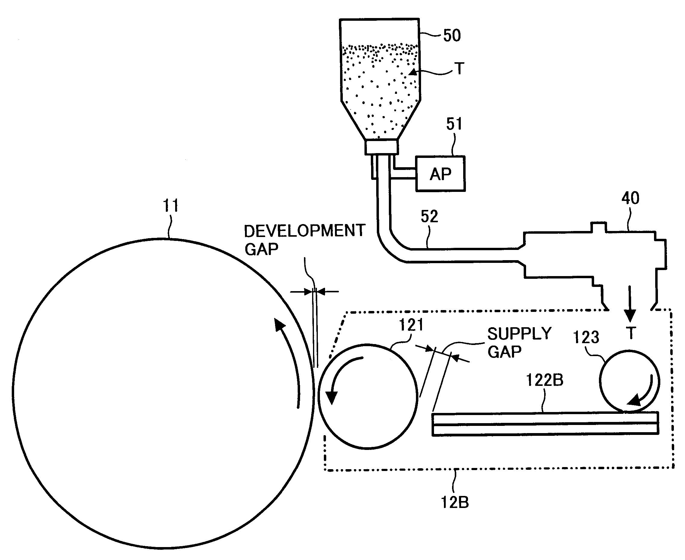
[0076]FIG. 6 illustrates the development unit and the surrounding elements thereof in accordance with the second preferred embodiment of the present invention. As shown, a development unit 12B includes a powder pump 40. The powder pump 40 feeds the toner T held in a toner cartridge 50, arranged separately from the development unit 12B, into the development unit 12B. The toner T in the toner cartridge 50 is fluidized by air supplied by an air pump 51, and is then supplied to the development unit 12B through a conveyance tube 52 under sucking pressure of the powder pump 40. In the second preferred embodiment of the present invention, a spherical toner is used.

[0077]L...

third preferred embodiment

[0087]A toner consumed portion where no toner is present and a toner unconsumed portion where toner remains coexist on the surface of the development roller 121 after the development roller 121 has passed by the development zone. When such a development roller 121 reaches the toner supply zone, toner is supplied by the electrostatic conveyance member 122. It is difficult to eliminate the difference in the amount of toner sticking to the development roller 121 between the toner consumed portion and the toner unconsumed portion. If the portions different in the amount sticking toner are left on the surface of the development roller 121, density non-uniformities and residual images take place when the development process is performed in the development zone with the facing photoconductive drum 11. The contact development process with the development roller 121 remaining in contact with the photoconductive drum 11 is more adversely affected by the non-uniformities of thin layer of toner...


PUM


Abstract

A toner contained in a hopper is fed to an electrostatic conveyance member by a supply roller. With an actuator of the electrostatic conveyance member functioning, the toner is conveyed while being electrically charged at the same time, and is then supplied to a development roller. A thin layer of toner is formed on the development roller under the effect of an electric field. Since the toner is formed and charged without a mechanical layer thickness controlling member such as a doctor blade, mechanical stress acting on the toner is reduced.

Description

BACKGROUND OF THE INVENTION[0001]1. Field of the Invention[0002]The present invention relates to a method and apparatus for image forming, and more particularly to a method and apparatus for image forming capable of effectively reducing mechanical stresses to developers during a transportation for a development to reproduce a superior quality image.[0003]2. Description of the Related Art[0004]A development device using a dry developer containing at least a toner is known in the field of an image forming apparatus using an electrophotographic technique, such as a copying apparatus, a facsimile machine, or a printer. In a known development device, a toner agitated in the development unit is deposited on the surface of a developer carrying member such as a development roller or a development sleeve, is formed in a uniform thin layer by a thin layer forming member such as a thin layer forming blade, and is conveyed to a development zone facing a photoconductive body as a latent image ca...

Claims


Application Information

Patent Timeline
Patent Type & Authority Patents(United States)
IPC IPC(8): G03G15/08G03G9/08G03G15/06H02N1/00
CPCG03G15/0808
Inventor AOKI, KATSUHIROKAI, TSUKURUIKEGUCHI, HIROSHI
Owner RICOH KK
Learn More