Method and apparatus for controlling time-scale modification during multi-media broadcasts

a multi-media and time-scale technology, applied in the field of multi-media broadcasting and presentation of broadcast multimedia, can solve the problems of poor playback effect, little or no interest, and the viewer/listener must wai

Inactive Publication Date: 2006-08-29
VIRENTEM VENTURES
View PDF23 Cites 66 Cited by
  • Summary
  • Abstract
  • Description
  • Claims
  • Application Information

AI Technical Summary

Problems solved by technology

There are several disadvantages inherent in both of these techniques.
A prime disadvantage of batch playback is that the viewer / listener must wait for the entire work to be downloaded before any portion of the work may be played.
This can be tedious since the viewer / listener may wait a long time for the transmission to occur, only to discover that the work is of little or no interest soon after playback is initiated.
However, a disadvantage of streaming is that playback is often interrupted when the flow of data is interrupted due to network traffic, congestion, transmission errors, and the like.
These interruptions are tedious and annoying since they occur randomly and have a random duration.
In addition, intermittent interruptions often cause the context of the playback stream to be lost as the viewer / listener waits for playback to be resumed when new data is received.
A further disadvantage of streaming is that a user or client is required to poll for additional data according to its rate of use of the data.
A further disadvantage in broadcasting audio or audio-visual works using prior art methods occurs when clients request data asynchronously from the media server.
A major problem with this prior art method is that clients must join a re-broadcast in the middle of the audio or audio-visual work currently being broadcast, or wait for the next re-broadcast to begin to view the start of the audio or audio-visual work.
A major problem with this second prior art method is that the media server must monitor, track and fulfill the request of each client requesting data individually.
This causes a dramatic increase in server load during heavy use since multiple requests arrive simultaneously, and storage access patterns and broadcast load vary widely.
As a result, the media server's capacity to serve a number of clients in a reasonable time is limited.

Method used


Image

  • Method and apparatus for controlling time-scale modification during multi-media broadcasts
  • Method and apparatus for controlling time-scale modification during multi-media broadcasts
  • Method and apparatus for controlling time-scale modification during multi-media broadcasts

Examples


embodiment 1000

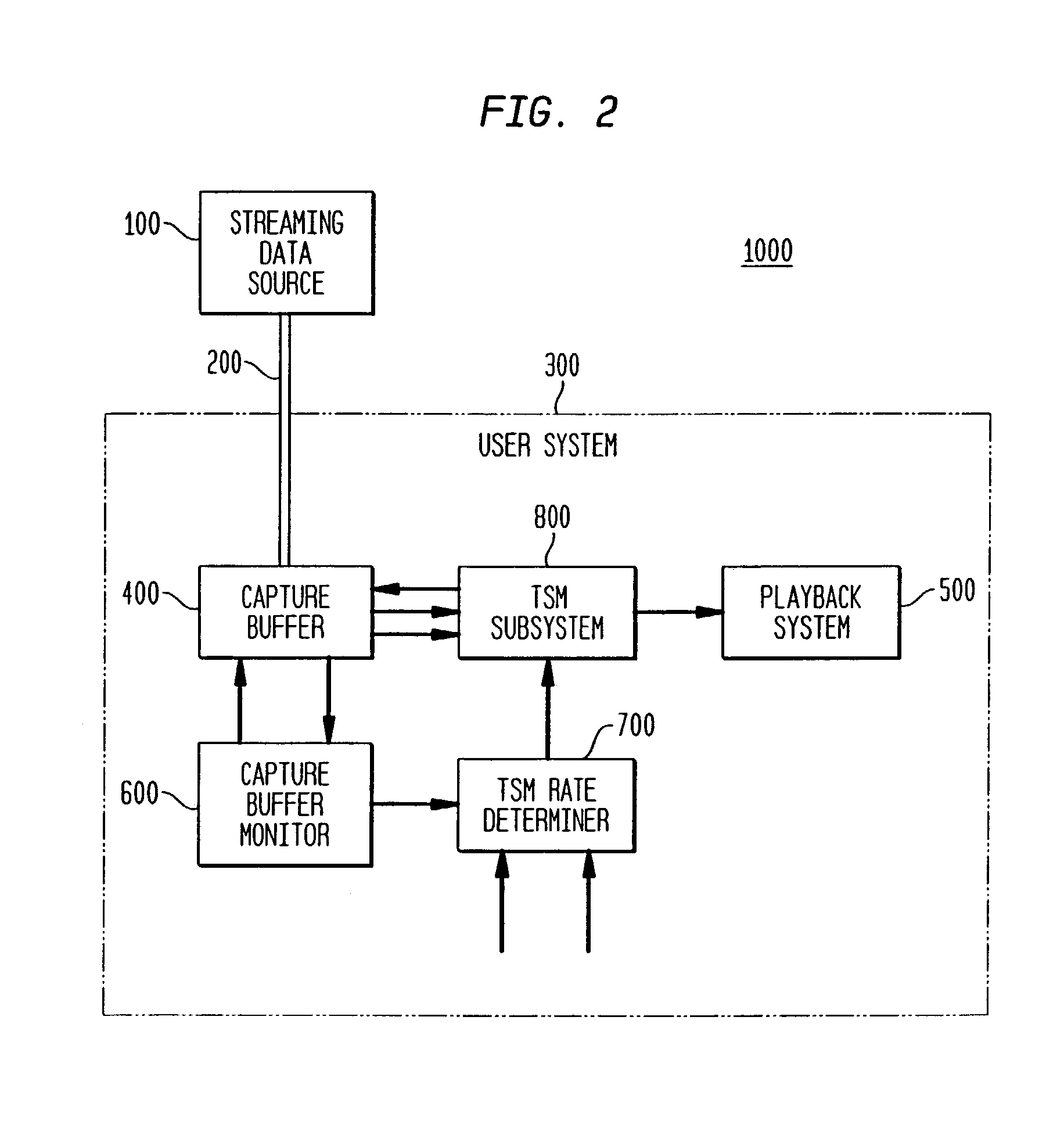
[0033]FIG. 2 shows a block diagram of embodiment 1000 of the present invention which provides substantially continuous playback of an audio or audio-visual work received from a source having non-deterministic delays such as a server (for example, a file server or a streaming media server) broadcasting via the Internet. As shown in FIG. 2, streaming data source 100 provides data representing an audio or audio-visual work through network 200 to User System 300 (US 300), which data is received at a non-deterministic rate by US 300. Capture Buffer 400 in US 300 receives the data as input. In a preferred embodiment of the present invention, Capture Buffer 400 is a FIFO (First In First Out) buffer existing, for example, in a general purpose memory store of US 300.

[0034]In the absence of delays in arrival of data at US 300 from network 200, the amount of data in Capture Buffer 400 ought to remain substantially constant as a data transfer rate is typically chosen to be substantially equal t...

embodiment 3000

[0056]FIG. 7 shows a block diagram of embodiment 3000 of a media server which re-broadcasts an audio or audio-visual work at regular intervals. As shown in FIG. 7, Storage Device 3100 is a storage device of a type which is well known to those of ordinary skill in the art. Storage Device 3100 stores a representation (preferably a digital representation, or any representation that can be converted to a digital representation in accordance with methods which are well known to those of ordinary skill in the art) of an audio or audio-visual work or data of interest to a user (such as a stream of stock quotes, market data, advertisements, and so forth). Storage Device 3100 receives, as input, data requests from Work Streamer 3200, and provides, as output, the data requested.

[0057]As further shown in FIG. 7, Work Streamer 3200 receives as input: (a) a code (for example, a number) which represents a desired Re-broadcast Interval (“RBI”) (from Re-broadcast Interval Determiner 3700); (b) a co...

embodiment 4000

[0062]Conversely, components of embodiment 4000 may exist in separate locations connected to one another by a network or any other communication means (where the use of the term means is used in the broadest sense possible).

[0063]In accordance with this embodiment of the present invention, an audio or audio-visual work is encoded into data that is later decoded to recreate the original audio or audio-visual work. Those of ordinary skill in the art should readily appreciate that the amount of data that represents a particular portion of the audio or audio-visual work can be transmitted, re-broadcast, and / or accessed from Storage Device 3100 in a time interval that is significantly less than the playback time interval of the particular portion. FIG. 8A shows the playback time of segments (Seg0, Seg1, . . . , SegN) of an original audio or audio-visual work, plotted along time axis 3001. The segments are encoded as data in accordance with methods that are well known to those of ordinary...


PUM


Abstract

One embodiment of the present invention is a method for presenting broadcast information that comprises steps of: (a) receiving broadcast information; (b) receiving guidance information relating to presentation of the broadcast information; (c) paying for a capability to alter or override at least a portion of the guidance information; (d) receiving user input to alter or override at least some of the guidance information; (e) analyzing the guidance information, the capability, and the user input to provide one or more presentation rates; and (f) presenting the information at the one or more presentation rates.

Description

[0001]This is a continuation of a patent application entitled “Method and Apparatus for Controlling Time-Scale Modification During Multi-Media Broadcasts” having Ser. No. 09 / 325,245 which was filed on Jun. 3, 1999 now U.S. Pat. No. 6,598,228, which patent application was a continuation-in-part of a patent application entitled “Method and Apparatus for User-Time-Alignment for Broadcast Works” having Ser. No. 09 / 320,374 which was filed on May 26, 1999 now U.S. Pat. No. 6,934,759. This patent application is related to a patent application entitled “Method and Apparatus for Server Broadcast of Time-Converging Multi-Media Streams” having Ser. No. 09 / 320,008 which was filed on May 26, 1999 and is now U.S. Pat. No. 6,370,688.TECHNICAL FIELD OF THE INVENTION[0002]The present invention pertains to multi-media broadcast and presentation of broadcast multi-media. In particular, the present invention pertains to method and apparatus for controlling Time-Scale Modification of broadcast multi-med...

Claims


Application Information

Patent Timeline
Patent Type & Authority Patents(United States)
IPC IPC(8): H04N7/16H04N7/173H04L12/18H04L29/06H04L29/08H04N21/2343H04N21/235H04N21/238H04N21/262H04N21/266H04N21/435H04N21/44H04N21/4402H04N21/442H04N21/458H04N21/472H04N21/488H04N21/61H04N21/6332H04N21/643H04N21/654H04N21/84H04N21/845
CPCH04N21/47217H04N21/234381H04N21/235H04N21/23805H04N21/262H04N21/26208H04N21/26616H04N21/435H04N21/44004H04N21/440281H04N21/44209H04N21/458H04N21/47202H04N21/4882H04N21/6125H04N21/6332H04N21/643H04N21/654H04N21/84H04N21/8456H04L65/4076H04L65/604H04L65/80H04L67/325H04N21/4307H04N21/25866H04L29/06H04L12/18H04L29/06027H04L67/42H04L69/329H04N21/43072H04L65/764H04L65/611H04L67/62H04L9/40H04L65/1101H04L67/01
Inventor HEJNA, JR., DONALD J.
Owner VIRENTEM VENTURES
Why Eureka
Try Eureka