

Directional flow flashing
a directional flow and flashing technology, applied in the field of flashings, can solve the problems of creating rot and/or damage to the subsurface or structural materials, and achieve the effects of preventing leakage of moisture, easy installation, and low manufacturing cos
- Summary
- Abstract
- Description
- Claims
- Application Information
AI Technical Summary
Benefits of technology
Problems solved by technology
Method used
Image

Examples
Embodiment Construction
)
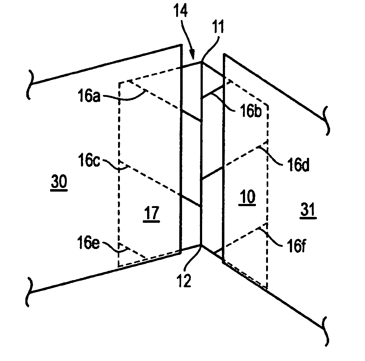
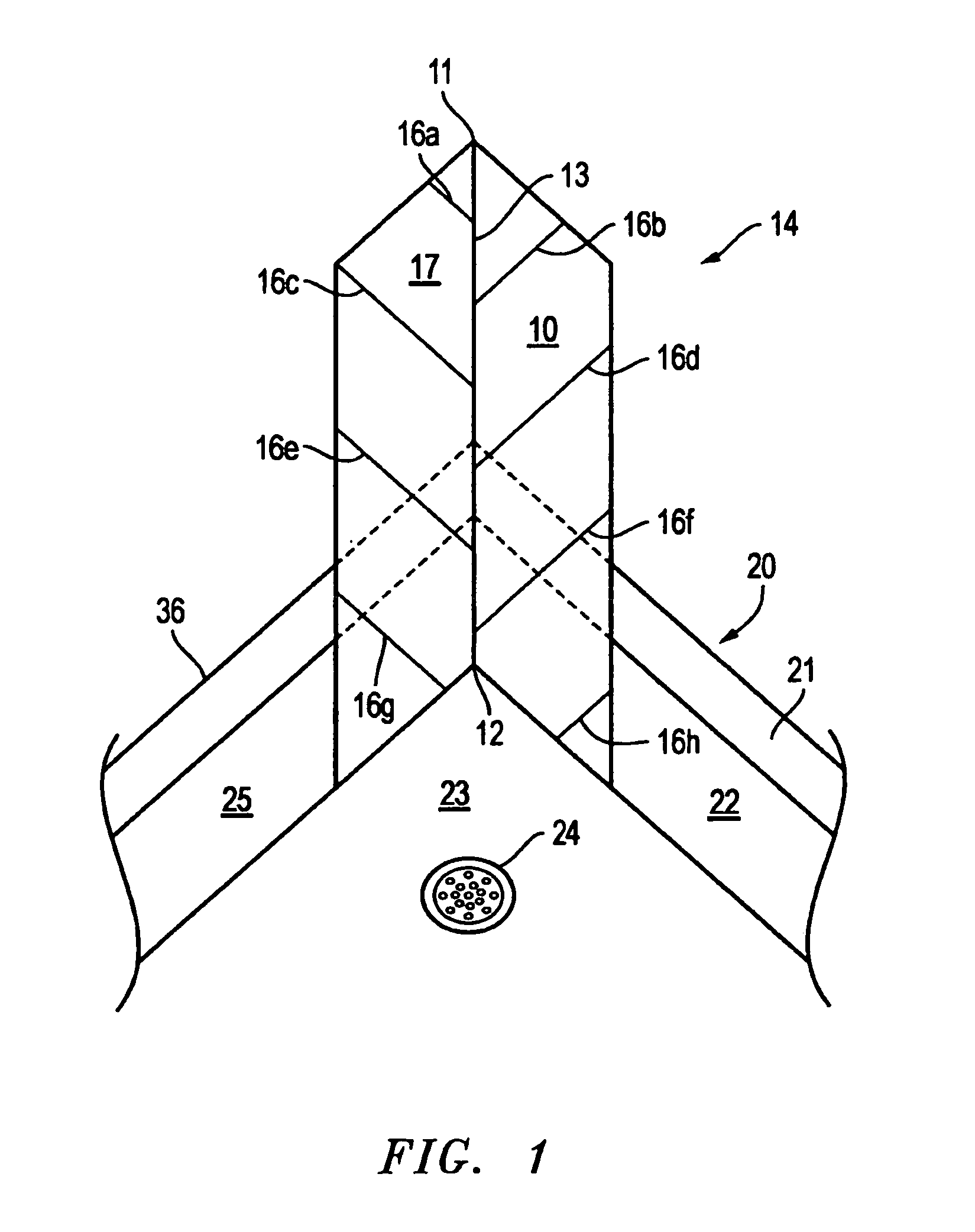
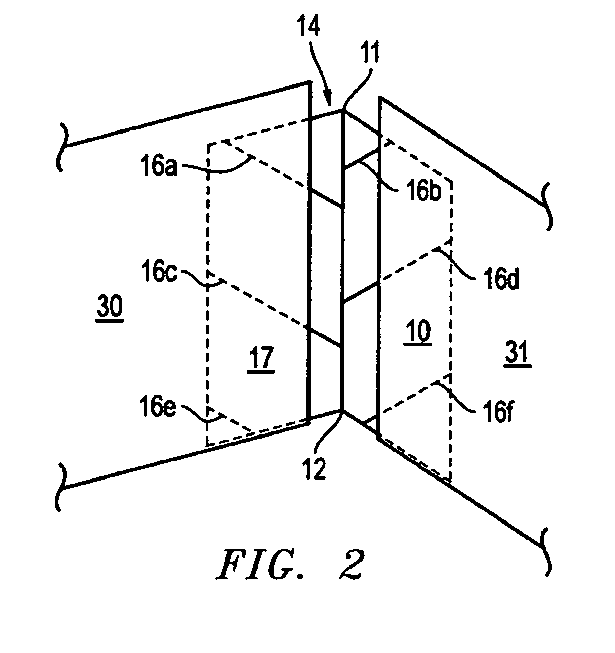
[0055]As seen in FIG. 1, the instant invention is of a flashing 14 with directional vanes, ribbing, scoring or etchings 16a–16h on its working surface. In the preferred embodiment, the flashing 14 of the instant invention is of a single piece construction, metal or plastic, with a center fold, line 11–12, whereby two interior surface panels 10 and 17 are discernable. While no specific angle exists between the two working surface panels 10 and 17, in the embodiment depicted in FIG. 1, where the flashing 14 is standing vertically in a corner of a shower tub enclosure 20, such angle approximates 90°. In FIG. 1, the center fold, line 11–12, is depicted as a crisp line approximately midway between the two side panels 10 and 17 of the flashing 14. No such limitation exists in the invention as the directional vanes, ribbing, scoring or etchings 16a–16h on the working surface of the flashing 14 will effectively direct the flow of accumulated moisture even if the flashing 14 is semi-circula...
PUM
 Abstract
Description
Claims
Application Information