
Arrow rest for an archery bow

a technology for archery bows and rests, which is applied in the direction of spring guns, compressed gas guns, white arms/cold weapons, etc., can solve the problems of cumbersome and unreliable mechanical systems of this known type of design for moving the rest platform to a lowered position

Inactive Publication Date: 2006-09-05
TERRY EDGELL
View PDF12 Cites 19 Cited by
  • Summary
  • Abstract
  • Description
  • Claims
  • Application Information

AI Technical Summary

Benefits of technology

[0011]An advantage of the present invention is that the arrow rest platform is automatically accelerated to a lowered position upon shooting of the bow such that it does not interfere with the free flight of the arrow.
[0012]Yet another advantage is that the actuator which moves the second sear to the disengaged position may be configured as a rotary actuator, linear actuator, or other suitable actuator.
[0013]Yet another advantage is that the arrow support platform may be configured as a plate, pair of pins, or other suitable arrow rest platform, depending upon the particular configuration.
[0014]Still another advantage is that the acceleration rate of the arrow rest platform between the raised support position and the lowered position may be adjusted depending upon the characteristics and attachment locations of the spring.
[0015]A further advantage is that the timing of the disengagement of the trigger sear can be adjusted.

Problems solved by technology

However, the mechanics of this known type of design for moving the arrow rest platform to a lowered position has proved to be cumbersome and somewhat unreliable.

Method used


Image

  • Arrow rest for an archery bow
  • Arrow rest for an archery bow
  • Arrow rest for an archery bow

Examples


Embodiment Construction

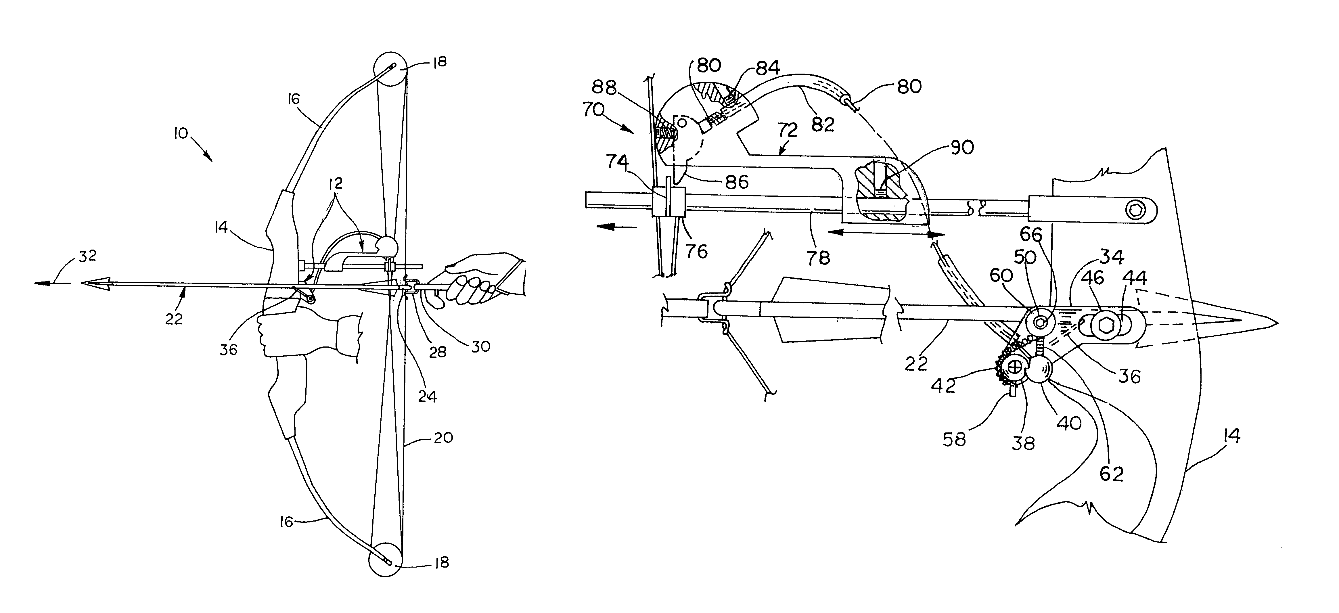
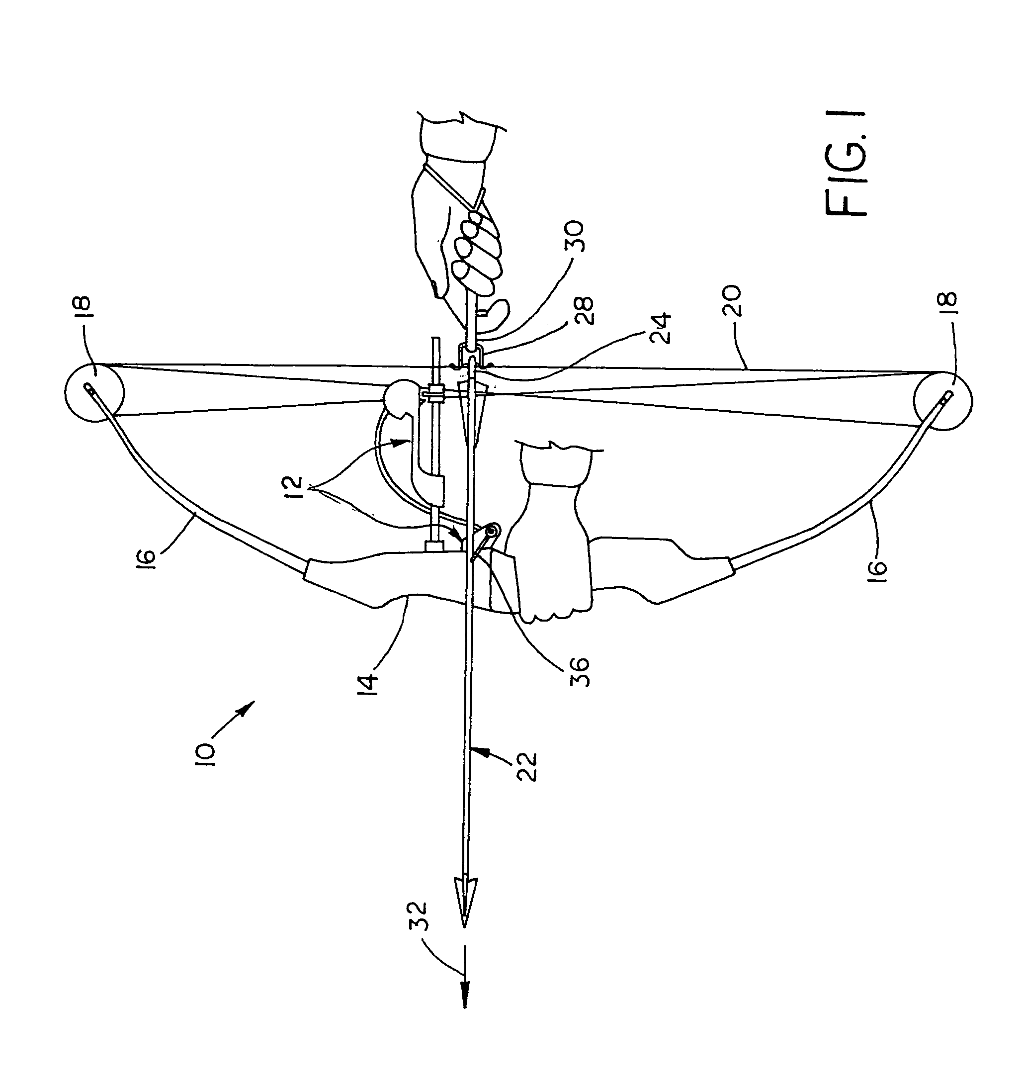
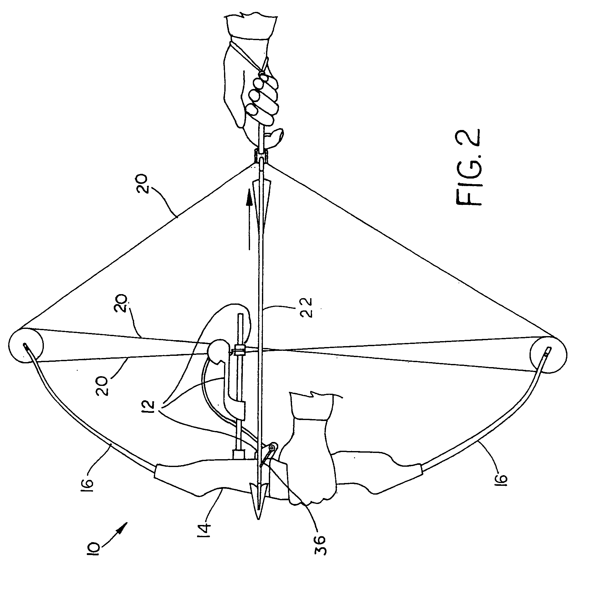
[0024]Referring now to the drawings, and more particularly to FIG. 1, there is shown an embodiment of an archery bow 10, incorporating an embodiment of an arrow rest assembly 12 of the present invention.

[0025]In the embodiment shown, bow 10 is a compound bow, but may be differently configured depending upon the application. For example, bow 10 may be a recurve or other type of bow. Bow 10 includes a riser 14 and a pair of flexible limbs 16 extending oppositely from riser 14. At the distal end of each limb 16 is a single rotating member 18, such as a pulley (as shown), or a cam wheel (not shown). At least one string 20 wraps around rotating members 18 and biases limbs 16 to a preloaded state.

[0026]Arrow rest assembly 12 is coupled with riser 14 and supports an arrow 22. Arrow 22 has a rear end with a nock 24 which is associated with a nock set 28 on string 20. Nock set 28 is engaged by a hand release 30 during use. Arrow 22 carried by arrow rest assembly 12 defines a trajectory plane...


PUM


Abstract

An archery bow includes a riser and a pair of flexible limbs extending from the riser, each limb having a distal end. At least one string extends between the limb distal ends and is movable between a drawn position and a fired position. A drop-away arrow rest mounted to the riser is movable between a raised position and a lowered position. The arrow rest is biased to the lowered position and includes a trigger sear for maintaining the arrow rest in the raised position. A cable guard arm is attached to and extends from the riser. A trigger assembly is carried by the cable guard arm and associated with the trigger sear. A trigger release is carried by and slidable along the cable guard arm. The trigger release is coupled with at least one string. The trigger release engages the trigger assembly and thereby disengages the trigger sear upon movement of the at least one string from the drawn position to the fired position.

Description

CROSS REFERENCE TO RELATED APPLICATIONS[0001]This is a non-provisional application based upon U.S. provisional patent application Ser. No. 60 / 515,196, entitled “ARROW REST FOR AN ARCHERY BOW”, filed Oct. 28, 2003; and a continuation-in-part of U.S. patent application Ser. No. 10 / 614,608, entitled “ARROW REST FOR AN ARCHERY BOW”, filed Jul. 7, 2003 now U.S. Pat. No. 6,820,607.BACKGROUND OF THE INVENTION[0002]1. Field of the Invention[0003]The present invention relates to archery equipment, and, more particularly, to arrow rests for archery equipment.[0004]2. Description of the Related Art[0005]Devices are known which provide improved accuracy for individuals target shooting and hunting with archery equipment. For example, bow sights have long been used to provide improved accuracy of an archery bow. A rear sight may be in the form of a bow string mounted peep sight having a small hole which is aligned with a forward sight pin mounted on the bow riser for substantially increasing the ...

Claims


Application Information

Patent Timeline
Patent Type & Authority Patents(United States)
IPC IPC(8): F41B5/22
CPCF41B5/143
Inventor TERRY, EDGELL
Owner TERRY EDGELL
Learn More