Toy gun having dual actuating manners

Inactive Publication Date: 2006-09-05
INCORN HOBBY
View PDF1 Cites 60 Cited by
  • Summary
  • Abstract
  • Description
  • Claims
  • Application Information

AI Technical Summary

Benefits of technology

[0010]A further objective of the present invention is to provide a toy gun that can shoot the plastic cartridges successively in an automatically controlled manner by the motor and the power switch and can shoot the

Problems solved by technology

However, the toy gun manually controlled by the user only shoots the cartridge once at a time, and cannot shoot the cartridge successively, thereby decreasing the amusement effect of the toy gun.
However

Method used


Image

  • Toy gun having dual actuating manners
  • Toy gun having dual actuating manners
  • Toy gun having dual actuating manners

Examples


Embodiment Construction

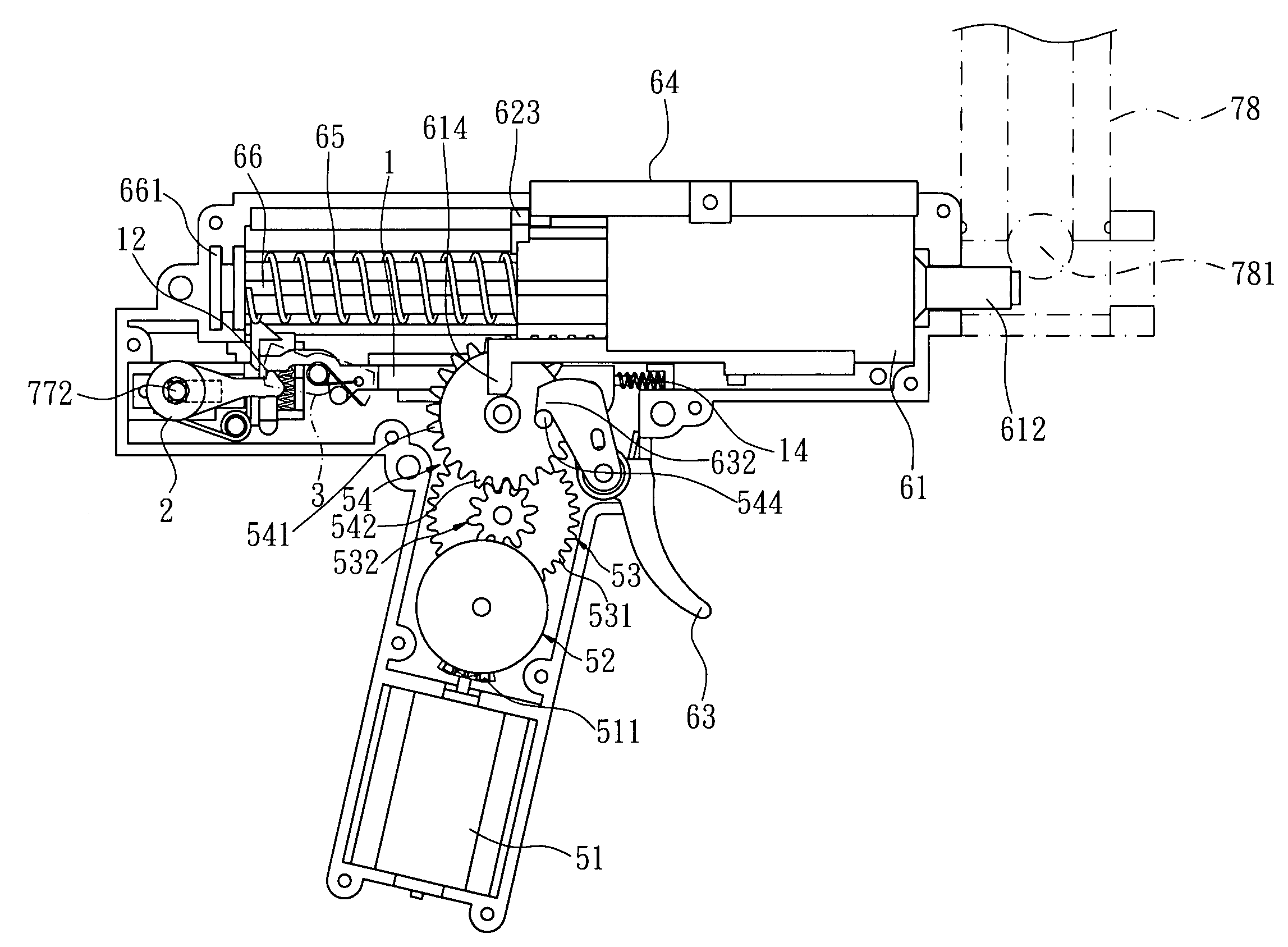
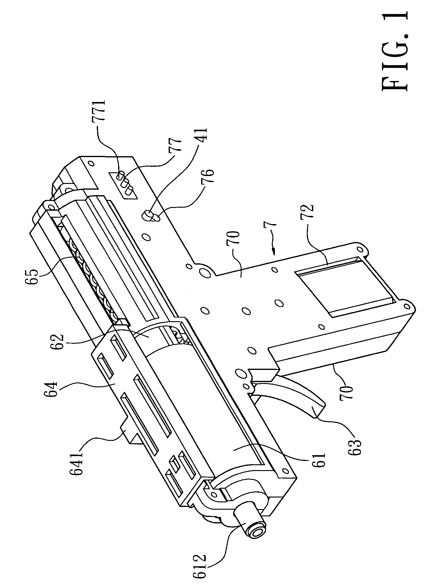
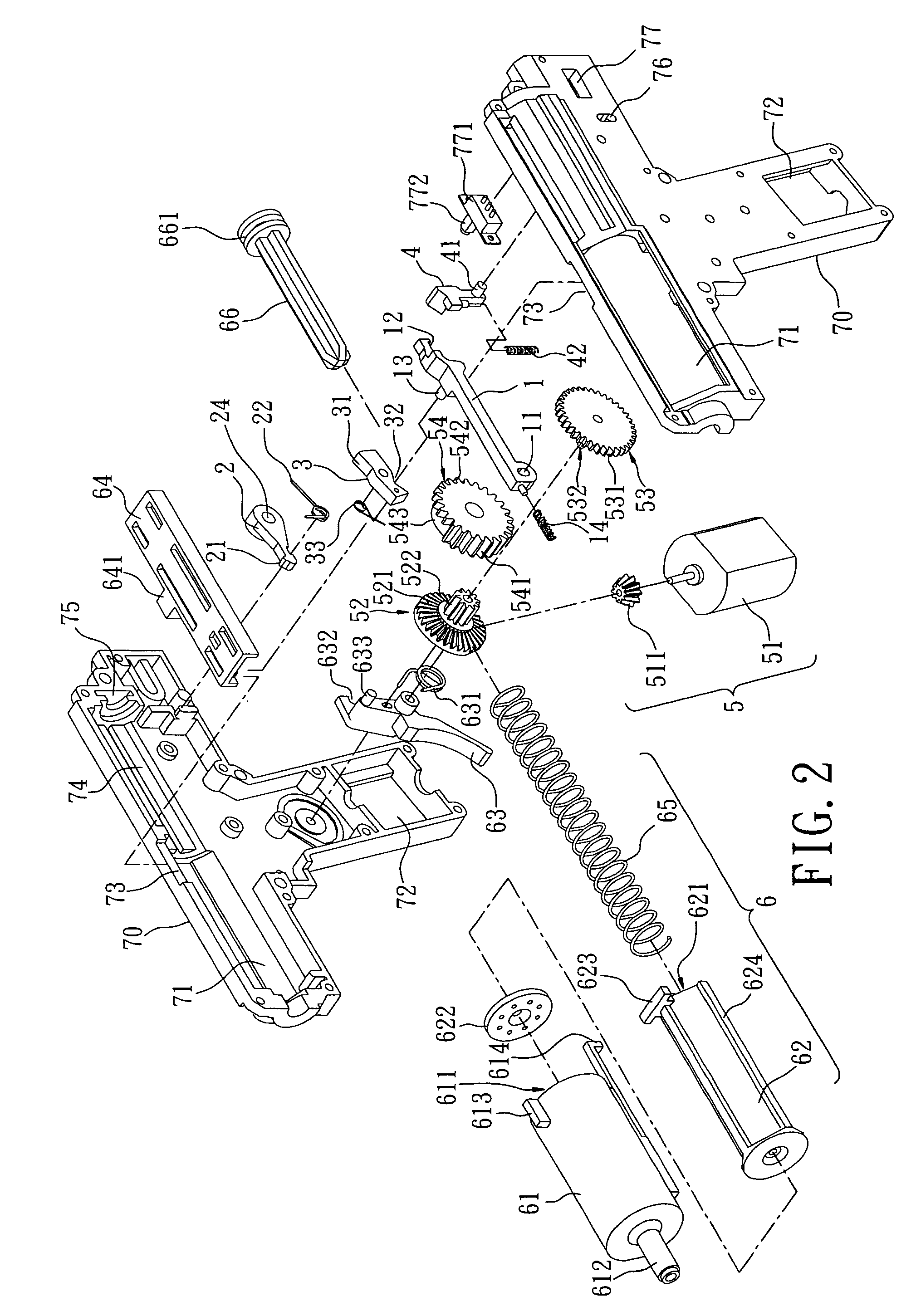
[0029]Referring to the drawings and initially to FIGS. 1–5, a toy gun in accordance with the preferred embodiment of the present invention comprises a driven lever 1, a driven member 2, a pivot member 3, a push block 4, a drive mechanism 5, a triggering device 6, and a housing 7.

[0030]The housing 7 includes two shells 70 combined with each other. The housing 7 is substantially T-shaped and has an upper portion formed with a hollow portion 71, two opposite side guide channels 74, a guide slot 73 located between the hollow portion 71 and the side guide channels 74 and a positioning recess 75 located at distal ends of the side guide channels 74. The housing 7 has a lower portion formed with a motor chamber 72. The upper portion of one of the two shells 70 of the housing 7 is formed with a horizontally extending power switch chamber 77 and a vertically extending control slot 76. A power switch 771 is mounted in the power switch chamber 77 of the housing 7.

[0031]The drive mechanism 5 inc...


PUM


Abstract

A toy gun includes a driven lever, a driven member, a pivot member, a push block, a drive mechanism, a triggering device, and a housing. Thus, the toy gun can shoot the plastic cartridges successively in an automatically controlled manner by the motor and the power switch and can also shoot the plastic cartridges individually in a manual manner by pulling the pull member and pressing the trigger, thereby enhancing the versatility of the toy gun, and thereby increasing the playing amusement of the toy gun.

Description

BACKGROUND OF THE INVENTION[0001]1. Field of the Invention[0002]The present invention relates to a toy gun and, more particularly, to a toy gun having dual actuating manners.[0003]2. Description of the Related Art[0004]A conventional toy gun comprises a housing, a piston, a spring, a magazine, and a trigger. The piston is pulled to compress the spring in the housing. When the trigger is pressed, the piston is released to release the spring so as to eject the cartridge contained in the magazine outward by the restoring force of the spring. However, the toy gun manually controlled by the user only shoots the cartridge once at a time, and cannot shoot the cartridge successively, thereby decreasing the amusement effect of the toy gun.[0005]A conventional motorized toy gun comprises a motor which drives a drive mechanism to pull the piston to compress the spring in the housing. Thus, the motorized toy gun can shoot the cartridge successively, thereby increasing the amusement effect of th...

Claims


Application Information

Patent Timeline
IPC IPC(8): F41B11/00A63H5/04F41B7/08F41B11/50F41B11/643F41B11/646F41B11/71
CPCF41B7/00
Inventor YANG, CHUNG-KUAN
Owner INCORN HOBBY
Why Eureka
Try Eureka