Recording tape cartridge

a technology of recording tape and cartridge, which is applied in the field of recording tape cartridge, can solve the problems of insufficient dustproofing measures with respect, and achieve the effect of excellent dustproof quality

Active Publication Date: 2006-09-05
FUJIFILM HLDG CORP +1
View PDF3 Cites 6 Cited by
  • Summary
  • Abstract
  • Description
  • Claims
  • Application Information

AI Technical Summary

Benefits of technology

[0013]In view of the aforementioned, an object of the present invention is to provide a recording tape cartridge having an excellent dustproof quality.
[0015]In the recording tape cartridge having the above-described structure, the releasing member, which holds the braking member at the rotation permitted position, is disposed at the inner side of the guide wall portion which stands erect at the floor portion of the reel hub. Therefore, a slight gap, which enables movement of the releasing member, exists between the releasing member and the guide wall portion. Dust and the like can enter in from this gap. However, the tubular wall portion, which is formed at the braking member, overlaps with the outer side of the guide wall portion, at least at the rotation locked position. Therefore, even if dust or the like entering in from the gap makes it way to the top surface of the guide wall portion, further penetration thereof is suppressed by the tubular wall portion. Accordingly, the dustproof quality is improved, and adhesion of dust and the like to the recording tape is prevented.
[0017]The tubular wall portion is further inward than the engaging portion, i.e., the guide wall portion and the releasing member are further inward than the engaging portion. Therefore, the engaging portion can be formed in a continuous, annular form. Accordingly, the ability of the braking member to brake the reel can be improved.

Problems solved by technology

However, even with this structure, the dustproofing measures are not sufficient enough with respect to dust which enters in from the through holes 168A, 172A.

Method used


Image

  • Recording tape cartridge
  • Recording tape cartridge
  • Recording tape cartridge

Examples


Embodiment Construction

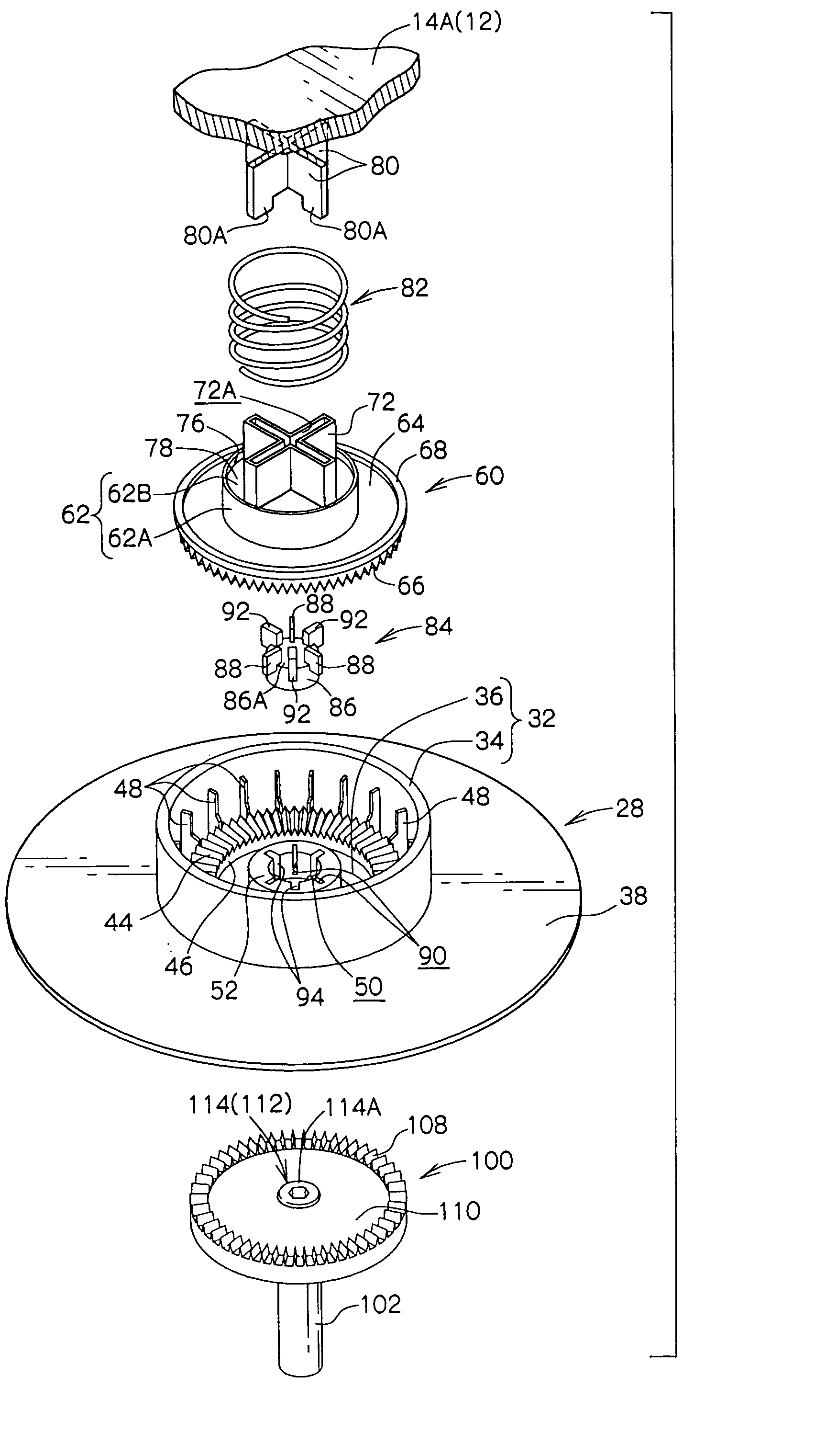
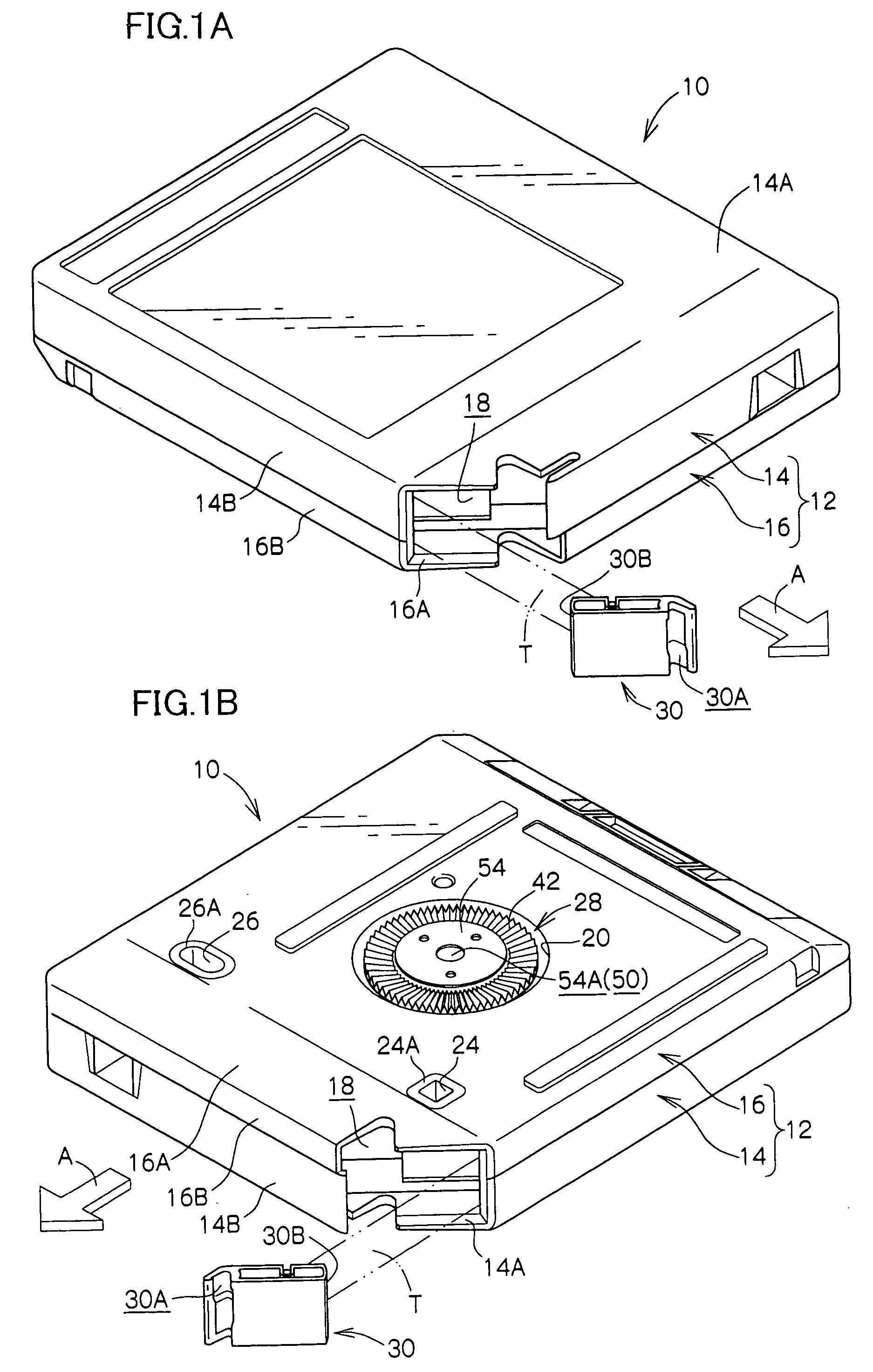
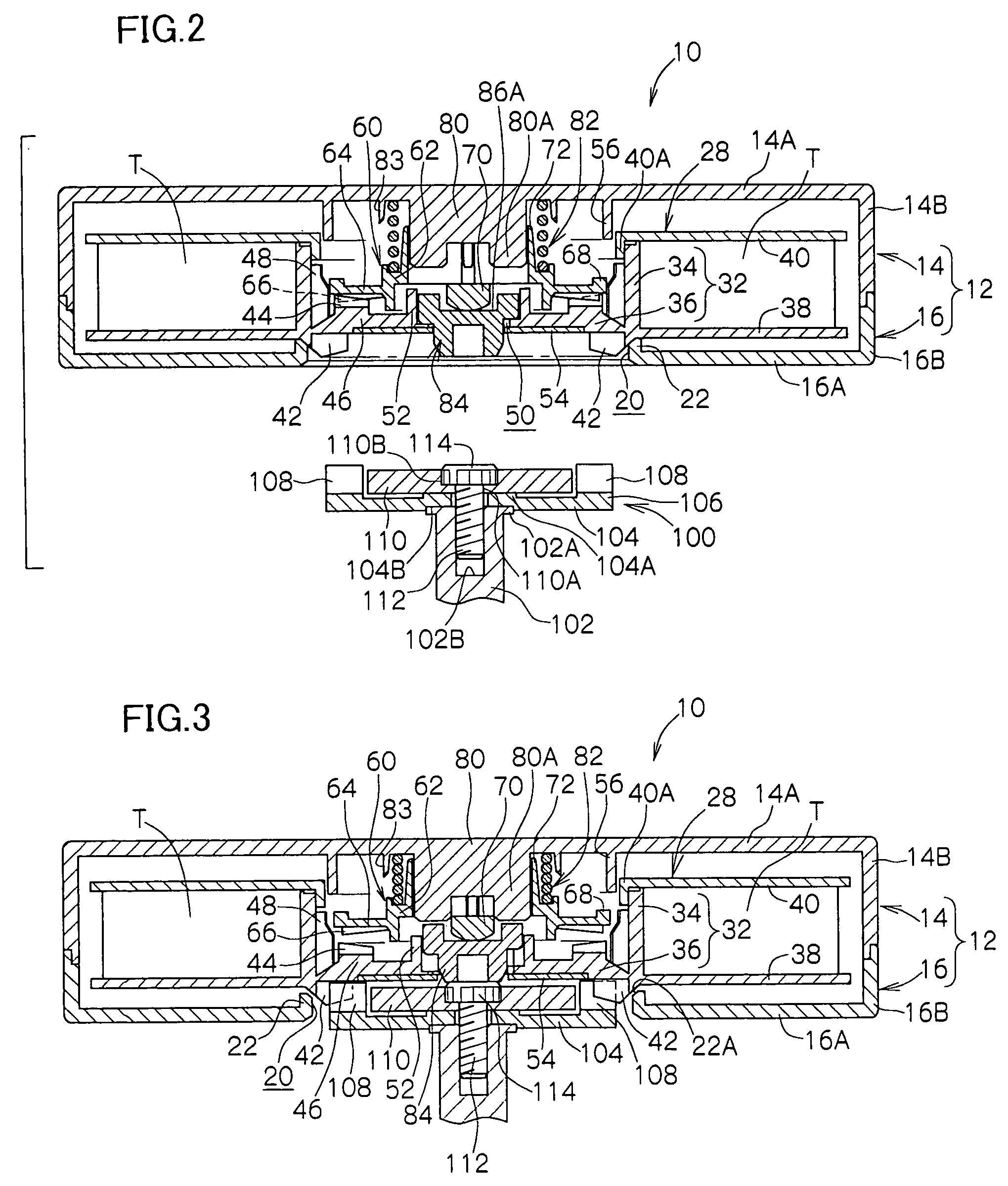
[0029]Hereinafter, a recording tape cartridge (magnetic tape cartridge) 10 relating to an embodiment of the present invention will be described on the basis of the embodiment illustrated in FIGS. 1A through 7B. Note that, for convenience of explanation, the direction of loading the recording tape cartridge 10 into a drive device is denoted by arrow A, and this direction of arrow A is the forward direction (front side) of the recording tape cartridge 10.

[0030]As shown in FIGS. 1A through 3, the recording tape cartridge 10 has a case 12. The case 12 is structured by an upper case 14 and a lower case 16 being joined together. Specifically, the upper case 14 is structured such that a substantially frame-shaped peripheral wall 14B stands erect along the outer edge of a ceiling plate 14A which is substantially rectangular in plan view. The lower case 16 is structured such that a peripheral wall 16B stands erect along the outer edge of a floor plate 16A which has a configuration substantia...


PUM

PropertyMeasurementUnit
thickness D1aaaaaaaaaa
thickness D2aaaaaaaaaa

Abstract

A recording tape cartridge has a reel accommodated within a case, an engaging portion provided at a floor portion of a reel hub; a braking member provided so as to be unable to rotate within the case, and approaching and moving away from the floor portion of the reel hub, and able to assume a rotation locked position at which the braking member engages with the engaging portion, and a rotation permitted position at which a state of engagement with the engaging portion is cancelled; and a releasing member disposed at an inner side of a guide wall portion provided at the floor portion of the reel hub, and when the reel is rotated, the releasing member holds the braking member at the rotation permitted position while abutting the braking member. The braking member has a tubular wall portion which overlaps with an outer side of the guide wall portion.

Description

CROSS-REFERENCE TO RELATED APPLICATION[0001]This application claims priority under 35 USC 119 from Japanese Patent Application No. 2003-43938, the disclosure of which is incorporated by reference herein.BACKGROUND OF THE INVENTION[0002]1. Field of the Invention[0003]The present invention relates to a recording tape cartridge accommodating, within a case, a single reel on which is wound a recording tape, such as a magnetic tape or the like, which is used as a recording / playback medium mainly of computers or the like.[0004]2. Description of the Related Art[0005]Conventionally, recording tape cartridges (magnetic tape cartridges) have been known in which a magnetic tape, which is used as a data recording / playback medium of a computer or the like, is wound on a single reel, and the reel is accommodated in a case formed of synthetic resin. In such a recording tape cartridge, as shown in FIG. 8, at a reel 160, a reel hub 162 and a lower flange portion 164 are molded integrally of a synthe...

Claims


Application Information

Patent Timeline
Patent Type & Authority Patents(United States)
IPC IPC(8): G11B23/04G11B23/027G11B23/107
CPCG11B23/043G11B23/107
Inventor ISHIHARA, YUSUKEHIRAGUCHI, KAZUOIINO, WATARU
Owner FUJIFILM HLDG CORP
Why Eureka
Try Eureka