[0002]The child seat and the method for child-seat detection according to the present invention have the advantage over the related art that they provide a simplified system for child-seat detection. It is distinguished in that a radio-identification module, which includes an identifier, is preferably introduced in the fabrics of the child seat. The radio-identification chip transmits a radio signal, which includes the identifier on the basis of which the child seat is detected, this transmission taking place continuously or intermittently, without any request. For that reason, the radio-identification chip is configured as transmitter module only and has no receiver structures. On the other hand, a receiver structure, but not necessarily a transmitter structure, is present in the vehicle seat. The radio identification according to the present invention is therefore achieved solely by a radio transmission from the child seat to the vehicle seat. Another advantage is that the simple, uncomplicated methodology applies to all child-seat manufacturers, so that a child seat specified by the vehicle manufacturer must not necessarily be purchased. Another advantage is that no intervention in the design of the child seat is required which, if necessary, also allows retroactive fitting using appropriate fabrics.
[0004]It is particularly advantageous that the radio-identification chip is woven into the fabric itself. The radio-identification chip module may be bonded to the conductive web strips as it happens in wire-bonding methods. As an alternative, a flexible plastic foil, similar to a flexible circuit board, having attached connection pads may be used. In both cases the radio-identification chip and the connecting region are hermetically encapsulated. The energy for the radio-identification chip in the fabrics may be provided either by an energy store such as a battery or an accumulator, which is rechargeable, or by a thermogenerator. Since the human body generates energy in the form of heat on the order of several 10 watts, it makes sense to utilize a portion of this energy. Miniaturized thermogenerators, for instance, are able to obtain electrical energy from the temperature difference between the body surface and the ambient environment. Thermogenerators are simple electrical components made up of two different conductors or semiconductors. They are joined to one another at one end in each case and in this way form a thermo pair. If there is a temperature difference between the two sides of a thermo pair, an electrical voltage will be generated due to the so-called Seebeck effect, and current will be able to flow through a connected load, which in this case is the radio-identification chip module. A thermogenerator is made up of a multitude of thermo pairs, all of which are electrically interconnected in series and arranged side-by-side, in meander-shape, in order to ensure optimum space utilization. In this way, high overall voltages and electrical outputs are achieved. In contrast to batteries, these thermogenerators have very advantageous characteristics: They are washable, robust, they are made of environmentally friendly materials and have a practically unlimited service life. When thermogenerators are implemented in textiles, it is important to select locations where the occurring temperature differences between the inside and outside are as high as possible. For a reliable, constant energy supply the generated temperature profiles at moderate ambient temperatures and with thin clothing must be taken into account. Relatively low temperature differences of four to six Kelvin are measured at the wrists, which generally have low skin temperature. In contrast, the neck region reaches very high values. A collar in close contact with the skin generates temperature differences of 17 Kelvin, which makes this region very attractive for obtaining energy. However, this is in some respects not so attractive for a child seat. Nevertheless, the results generally indicate that temperature differences of at least 5 Kelvin are attained in the clothing, even at moderate ambient temperatures.
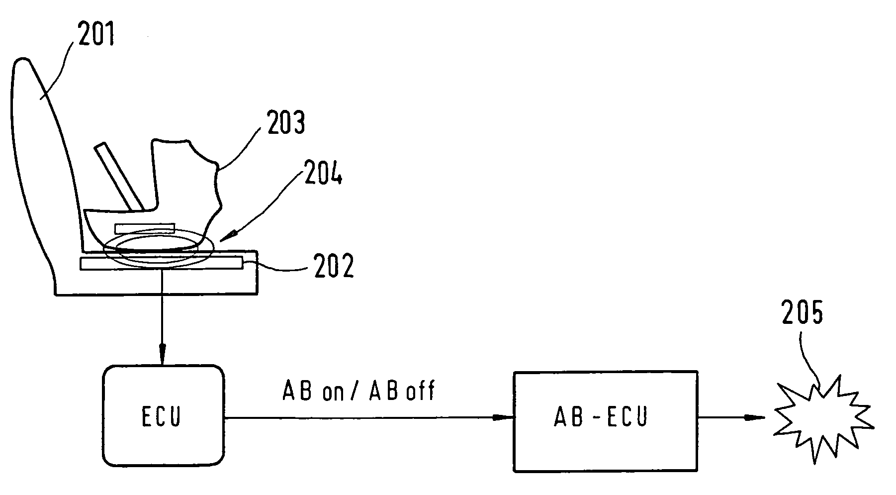
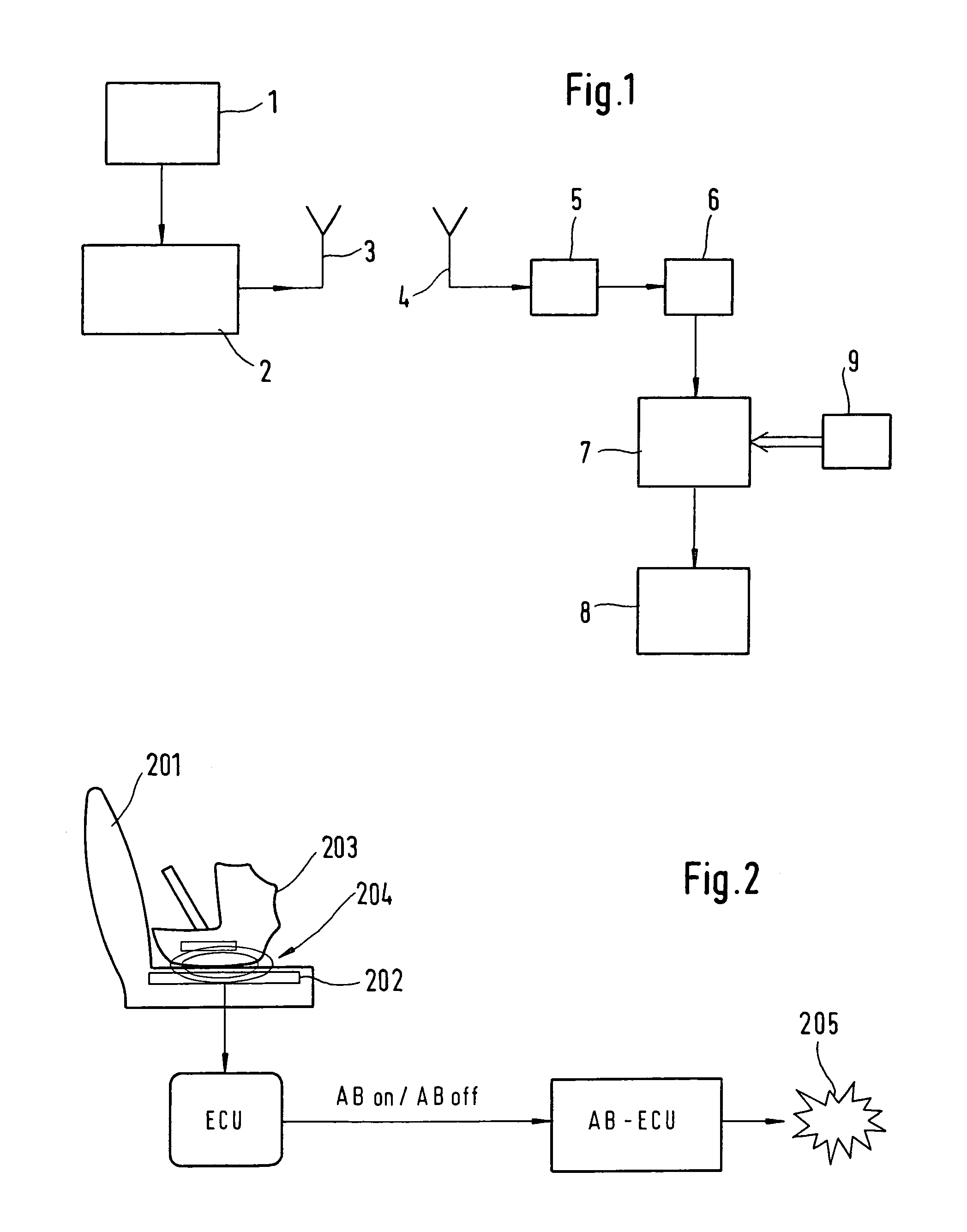
[0006]The child-seat detection according to the present invention may advantageously be combined with other methods for child-seat detection with the goal of achieving plausibility or increased reliability of the child-seat detection. For instance, it may be connected to a child-seat detection that determines the child seat via the seat-pressure profile, for example with the aid of a sensor mat, or which has an optical identification system for child-seat detection, i.e., a video sensor.

