
Implantable vascular access device

a technology of vascular access device and implantable catheter, which is applied in the direction of suction device, medical device, other medical device, etc., can solve the problems of patient morbidity and mortality, high cost, and prone to clotting of fistulas such as thes

Active Publication Date: 2006-09-05
MILLER MEDICAL LLC
View PDF11 Cites 24 Cited by
  • Summary
  • Abstract
  • Description
  • Claims
  • Application Information

AI Technical Summary

Benefits of technology

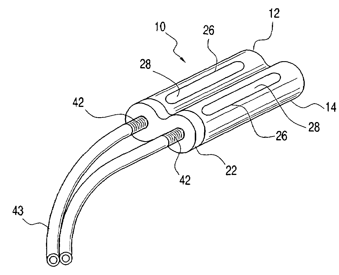
[0019]It is, therefore, an object of the present invention to provide an implantable dual chambered catheter device. The device includes a first chamber and a second chamber integrally joined. The first chamber includes a hollow first elastomeric member contained within a first slotted outer housing. A first end of the first elastomeric member is fitted with a first end cap shaped and dimensioned to accept conventional catheter tubes and the second end of the first elastomeric m...

Problems solved by technology

However, fistulas such as these are prone to clotting and have an average life span of only 1 to 1½ years.
Unfortunately, infection, skin loosening, and the possibility of catheters coming apart have resulted in great expense, as well as patient morbidity and mortality.
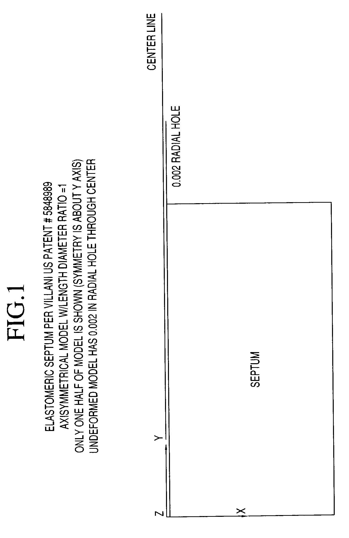
Experiments have shown that repetitive punctures of a septum with large diameter needles will result in the leakage of blood through the septum.
However, it is highly unlikely that the structure disclosed by Loiterman would in fact work as proposed for an extended period of time.
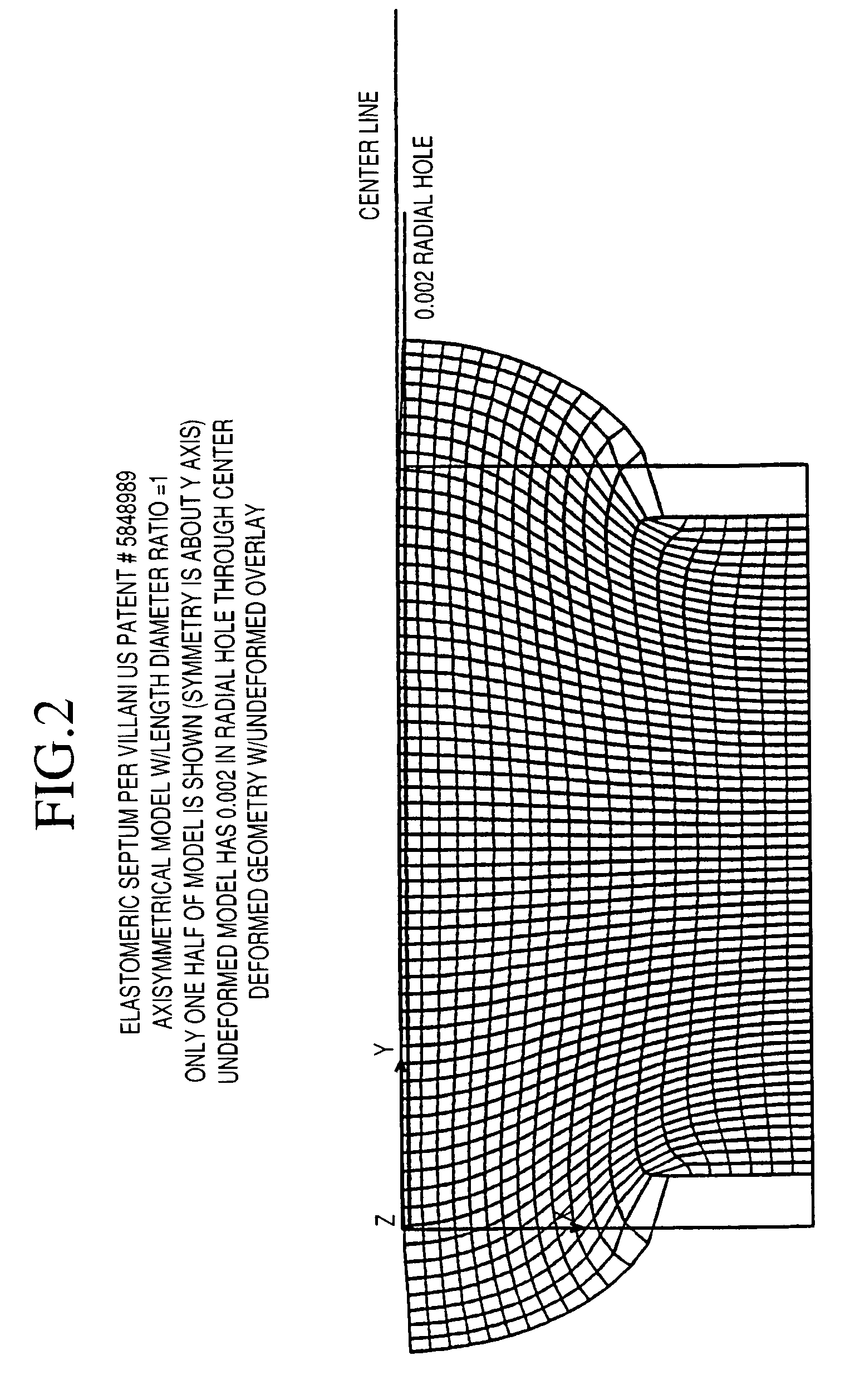
That is, the stress distribution within the septum tends to keep the hole open, thereby permitting the passage of blood through the open hole (which is highly undesirable).
The finite element analysis of the Villani / Hilger design shows that the septum cannot be effectively sealed using this design.
Once a hole has been established in the septum by repeated needle punctures, the hole remains open and will permit an undesirable blood flow passage through the septum.

Method used


Image

  • Implantable vascular access device
  • Implantable vascular access device
  • Implantable vascular access device

Examples


Embodiment Construction

[0049]The detailed embodiments of the present invention are disclosed herein. It should be understood, however, that the disclosed embodiments are merely exemplary of the invention, which may be embodied in various forms. Therefore, the details disclosed herein are not to be interpreted as limited, but merely as the basis for the claims and as a basis for teaching one skilled in the art how to make and / or use the invention.

[0050]With reference to FIGS. 11, 12, 13 and 14, an implantable dual chambered catheter device 10 is disclosed. The catheter device 10 is a dual chambered device and includes first and second tubular chambers 12, 14 joined to form a single implantable catheter device 10. Each of the tubular chambers 12, 14 is generally composed of an elastomeric cylindrical member 16 contained within a slotted titanium outer cylinder 18. Since the first and second tubular chambers 12, 14 are identical, similar reference numerals are used to designate similar components of each cha...


PUM


Abstract

An implantable dual chambered catheter device includes a first chamber and a second chamber integrally joined. The first chamber includes a hollow first elastomeric member contained within a first slotted outer housing. A first end of the first elastomeric member is fitted with a first end cap shaped and dimensioned to accept conventional catheter tubes and the second end of the first elastomeric member is closed. The second chamber includes a hollow second elastomeric member contained within a second slotted outer housing. A first end of the second elastomeric member is fitted with a second end cap shaped and dimensioned to accept conventional catheter tubes and the second end of the second elastomeric member is closed. Needle access to the first and second chambers of the implantable catheter device is through respective slots formed within the first and second outer housings.

Description

CROSS REFERENCE TO RELATED APPLICATION[0001]This application is based upon U.S. Provisional Patent Application Ser. No. 60 / 277,955, filed Mar. 23, 2001, entitled “IMPLANTABLE CATHETER ASSEMBLY FOR HEMODIALYSIS”, which is currently pending.BACKGROUND OF THE INVENTION[0002]1. Field of the Invention[0003]The invention relates to an implantable catheter assembly for hemodialysis. More particularly, the invention relates to an implantable catheter assembly providing long or short term access via a needle wherein a puncture region is readily sealed after removal of the puncturing needle.[0004]2. Description of the Prior Art[0005]Patients with renal failure face certain death unless managed by either hemodialysis or peritoneal dialysis. Renal transplantation is the best, albeit less available, solution to this problem. As a result, various dialysis solutions have been developed. One current hemodialysis solution includes the surgical creation of an arterial to venous fistula using either n...

Claims


Application Information

Patent Timeline
IPC IPC(8): A61M39/04A61M1/16A61M1/36A61M31/00A61M39/02
CPCA61M1/3653A61M1/3661A61M39/0208A61M1/16A61M2039/0211A61M1/3656A61M1/3659
Inventor MILLER, STUART H.
Owner MILLER MEDICAL LLC
Learn More