Magnetic array implant

a technology of magnetic array and implant, which is applied in the field of magnetic array implants, can solve the problems of inability to understand, limited use of disclosed devices and methods for specific orthopedic problems, and general inpracticality of designs, so as to avoid potentially unpredictable implantation, facilitate implantation, and facilitate treatment

Inactive Publication Date: 2006-09-05
HYDE EDWARD R
View PDF50 Cites 65 Cited by
  • Summary
  • Abstract
  • Description
  • Claims
  • Application Information

AI Technical Summary

Benefits of technology

[0013]In another aspect of the invention, the magnets of the magnetic array may be secured into a housing, while maintaining the configuration and / or orientation thereof. By providing prearranged configuration and / or orientation thereto, the magnetic array can be readily adapted to treat variety of orthopedic conditions. This arrangement avoids potentially unpredictable implantation of individual magnets into different locations in the adjacent bone portions, simplifies the implantation procedure, reduces the time of the surgical procedure, minimizes complications following the surgery, facilitates the healing process, and provides a treatment option that is easier to perform and can be performed in a competent fashion by a greater number of surgeons.
[0014]In yet another aspect of the invention, the magnetic arrays are implanted into adjacent bone portions so as to control forces at the adjacent bone portions and / or to constrain the motion of adjacent bone portions in one or more dimensions. When one magnetic array is disposed in an opposed relationship to another magnetic array, the composite magnetic fields of each of the magnetic arrays interact with each other, and generate dynamically interacting magnetic fields between and / or around those magnetic arrays. Characteristics of the interacting magnetic fields can be specifically controlled by manipulating properties, shapes, and / or other characteristics of each individual magnet in each magnetic array, because the resultant of the interacting magnetic fields is a vector sum of the individual composite magnetic fields of each magnetic array. By manipulating the repulsive and / or attractive forces generated therebetween, the magnetic arrays can provide potential energy to do work along the axis parallel and orthogonal to the direction of the magnetic polarity, as well as provide rotational stability for particular array designs to the adjacent bone portions. This potential energy can be used to reduce the reactive force between the bone portions, and / or limit motion between the bone portions. According to the invention, the orthopedic magnetic apparatus including the foregoing magnetic arrays may be applied to various orthopedic conditions such as long bone fractures, carpal bone fractures, joint instability, early arthritis and end stage arthritis. They may also be used to augment the designs of other total joint components. In treating fractures, the magnetic arrays of the invention may be arranged to create dominant attractive force, thereby providing the structural and / or rotational stability thereto.
[0015]As indicated, in one aspect of orthopedic application of the present invention, the magnetic arrays described herein above may be applied to treat degenerative conditions such as arthritis. For such degenerative conditions the magnetic arrays may preferably be arranged to create dominant repulsive force, thereby providing potential magnetic energy to counteract mechanical forces along the axis parallel to composite magnetic force vector and provide stability along the axis orthogonal to the composite magnetic force vector. Benefits may be realized in reducing mechanical contact between the intact cartilage of the bone portions at a joint by reducing the joint reactive force and providing the additional means of control to diminish joint instability and / or the progression of joint disease. Moreover, the invention may be employed in or with prostheses to reduce the mechanical contact and the damage caused by friction between implanted prosthetic components, reducing joint reactive force, and providing the stabilizing capability, thereby decreasing pain associated with the end-stage arthritis and / or extending the functional life of the implanted components.

Problems solved by technology

The disclosed devices and methods had only limited uses for specific orthopedic problems.
However, these designs are generally not practically feasible due to errors or misconceptions related to the practical application of orthopedic surgical treatments or, more importantly, a lack of understanding concerning the properties of permanent magnets in relationship to the mechanical environment found in the human body, especially as they relate to the normal functions of bones and joints.

Method used


Image

  • Magnetic array implant
  • Magnetic array implant
  • Magnetic array implant

Examples


example

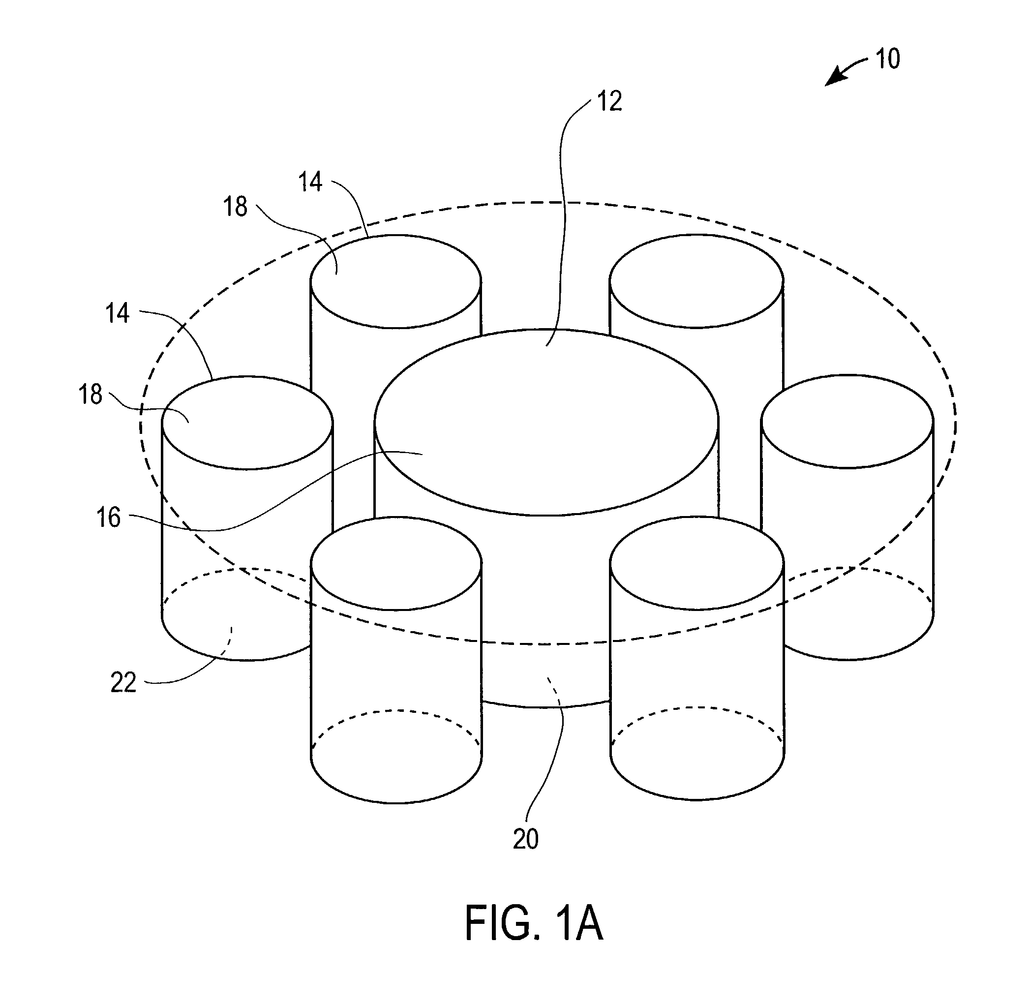
[0080]The following example represents the results of a computer model of a basic array design incorporating the fundamentals of the present invention. A computer simulation was performed to determine the magnitude of the repulsive vertical and radial force components of a representative magnetic arrays. As illustrated in FIG. 4A, apparatus 1100 includes first magnetic array 1110 and a second magnetic array 1120, where both arrays include the cylindrical center magnets 1112, 1122 positioned inside annular magnets 1114, 1124. The center magnets for each array were chosen to be one inch in diameter. The annular magnets were chosen to have an O.D. of two inches and an I.D. of one inch. Each array was one inch thick. In second array 1120, central magnet 1122 was made of NdFeB 48 and outer annular magnet 1124 was made of NdFeB 33. First array 1110 had the same configuration except that the magnet materials were reversed such that the stronger NdFeB 48 was at the outside. Both the first a...


PUM


Abstract

The present invention relates to apparatus and methods for stabilizing and or maintaining adjacent bone portions in predetermined desired relationships and for constraining one, two or three-dimensional motion and / or rotation of the adjacent bone portions. More particularly, the present invention relates to a magnetic apparatus with at least two magnetic arrays, each of which may include any number of magnets arranged in a predetermined manner and each magnetic array generating a magnetic field therearound. Once implanted and secured to the adjacent bone portions, the apparatus provides interacting magnetic fields in the area of the bone portions and transduces magnetic energy into mechanical energy and mechanical energy into potential magnetic energy, thereby reproducing functionally anatomic and / or anatomically advantageous arrangement of the bone portions.

Description

[0001]This application is a continuation application of U.S. patent application No. 09 / 594,356 filed Jun. 13, 2000, now U.S. Pat. No. 6,387,096 to Hyde, which is incorporated by reference herein in its entirety.FIELD OF THE INVENTION[0002]The present invention relates to apparatus and methods for stabilizing and maintaining adjacent bone portions in predetermined desired relationships and constraining one, two or three-dimensional motion and / or rotation of the adjacent bone portions. More particularly, the present invention relates to a magnetic apparatus with at least two magnetic arrays, each of which may include at least one magnet arranged in a predetermined manner and each magnetic array generating a magnetic field therearound. Once implanted and secured to the adjacent bone portions, the magnetic apparatus provides interacting magnetic fields in the area of the bone portions and transduces magnetic energy into mechanical energy and mechanical energy into potential magnetic ene...

Claims


Application Information

Patent Timeline
Patent Type & Authority Patents(United States)
IPC IPC(8): A61B17/56A61F2/30A61B17/64A61B17/68A61B17/72A61F2/00A61F2/02A61F2/38A61F2/40A61N2/00A61N2/06
CPCA61N2/06A61B17/68A61B17/72A61F2/3868A61F2/40A61B17/6425A61F2/3836A61F2/3859A61F2/3872A61F2/389A61F2/4059A61F2/4081A61F2002/30079A61F2002/30224A61F2002/30225A61F2002/30604A61F2002/30668A61F2002/30878A61F2002/30892A61F2002/4018A61F2002/4092A61F2210/009A61F2230/0069A61F2250/0001A61N2/008A61B17/6491
Inventor HYDE, JR., EDWARD R.
Owner HYDE EDWARD R
Why Eureka
Try Eureka